


2
85201A_RK5C_User Manual_02-2017_ENG
1. INTRODUCTION
The GEFRAN RK5C is a Digital Linear Position Sensor with CANopen interface. It implements the standard CANopen
communications protocol defined by CiA (CAN in Automation).
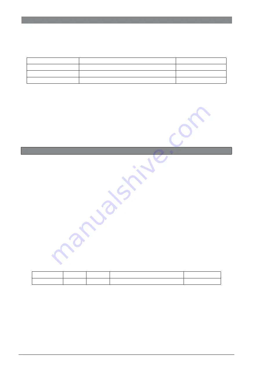
The CANopen standards supported by the device are listed in the following table.
CiA standard
Description
Version
DS 301
CANopen application layer and communication profile
4.2.0
DS 305
Layer setting services (LSS) and protocols
3.0.1
DS 406
Device profile for encoders
3.2.0
Table 1 - Supported CANopen standards
This document describes the CANopen implementation on the GEFRAN RK5C CANopen device. It is addressed to
CANopen network system integrators and to CANopen device designers who already know the content of the above-
mentioned standards defined by CiA.
The details of aspects defined by CANopen do not pertain to the purpose of this text. For further information on the
CANopen protocol see www.can-cia.de
2. GET STARTED PROCEDURE
2.1 NODE PARAMETERS SETTING
Before connecting the GEFRAN RK5C sensor to a fully configured and working CAN bus, some basic configuration
actions have to be performed. The configuration involves the Node-ID and the Baud rate of the CANopen device.
The configuration is mandatory if at least one of these conditions is true:
1) The Node-ID of the GEFRAN RK5C sensor is identical to the Node-ID of another CANopen device connected
to the CAN bus.
2) The GEFRAN RK5C sensor operates with a baud rate different from the CAN bus baud rate.
If the condition at point 2 in not verified, the configuration can also be performed on that CAN bus, but all the other
CANopen devices on the CAN bus should be taken in power-off state during the configuration process in order to avoid
errors or conflicts.
If the baud rate configuration has to be performed, the GEFRAN RK5C sensor must be connected to a CAN bus that
works at the same baud rate of the sensor. The baud rate of the actual CAN bus (with all devices connected to it) can also
be temporary set equal to the sensor baud rate until configuration is done. The configuration is made using LSS (Layer
Setting Services).
Switching to LSS configuration mode
The first operation is to switch the sensor into LSS configuration mode. If the sensor is the only device on the CAN bus
(with the LSS master), the LSS Switch State Global command can be used.
Source
COB-ID
DLC
Data
Destination
Controller
7E5h
08h
04h; 01h; 00h; 00h; 00h; 00h; 00h; 00h
Sensor
Figure 1 - LSS Switch State Global command
If there are other devices on the CAN bus (except the LSS master), the LSS Switch State Selective command must be
used. Refer to the LSS Services section for details.