gefran GTF Configuration And Programming Manual Download Page 36

36

80961F_MSW_GTF/GTF-Xtra_07-2018_ENG

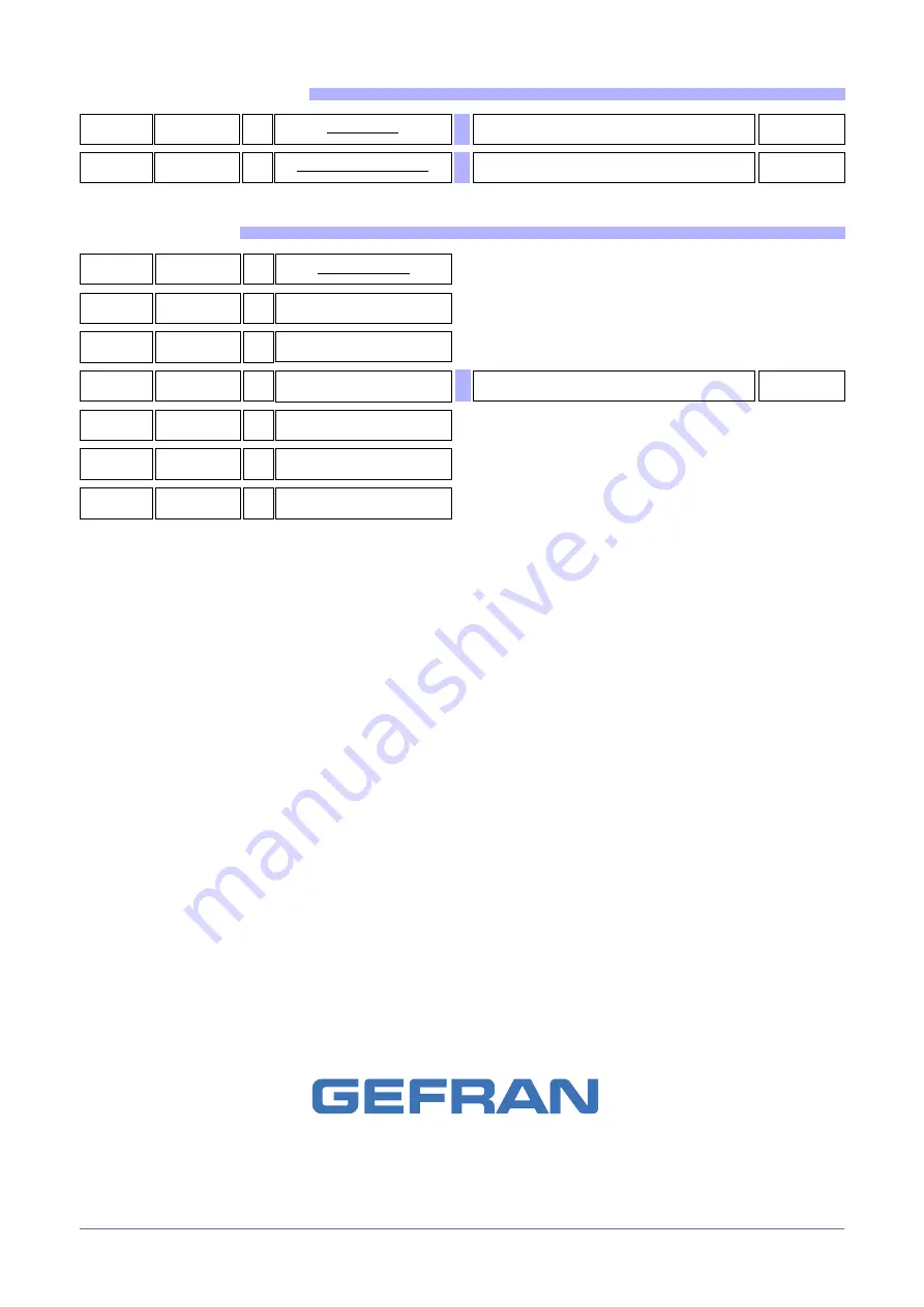
VIRTUAL INSTRUMENT CONTROL

42

hd.1

R/W

26

s.Io

R/W

Type of operation

Control input/outputs from serial

122

UPD

R

HW/SW INFORMATION

120

R

121

R

55

R/W

129

R

115

R

Status2

117

R

Status3

Software version code

Manufacturer - Trade Mark (Gefran)

Device ID (GTFP)

Current state (STATUS_W)

State saved in eeprom 

(STATUS_W_EEP)

GEFRAN spa

via Sebina, 74 - 25050 Provaglio d’Iseo (BS) Italy

Tel. +39 0309888.1 - Fax +39 0309839063

[email protected] - http://www.gefran.com

Summary of Contents for GTF

Page 1: ...d or property or to the product itself if the following terms and conditions are disregarded The Customer is obligated to respect trade secrets Therefore this manual and its attach ments may not be tampered with changed reprodu ced or transferred to third parties without GEFRAN s authorization CONFIGURATION AND PROGRAMMING MANUAL Software version 2 5x code 80961F 07 2018 ENG GTF and GTF Xtra POWER...

Page 2: ...2 80961F_MSW_GTF GTF Xtra_07 2018_ENG ...

Page 3: ...D 12 POWER ON LOAD 13 DIGITAL INPUTS 13 ALARMS 14 HB ALARM Heater Break Alarm 14 Power Fault ALARMS SSR_SHORT NO_VOLTAGE e NO_CURRENT 18 Overheat Alarm 18 Short circuit current alarm 19 Fuse open alarm 19 Overcurrent fault protection for GTF Xtra model 19 OUTPUTS 20 CONTROLS 21 AUTOMATIC MANUAL CONTROL 21 ON OFF SOFTWARE ENABLE DISABLE 21 START MODE 22 OPERATING HOUR METER 22 POWER CONTROL 23 VIRT...

Page 4: ... from installations configurations or programmings that are inappropriate imprudent or not conforming to the technical data supplied Prohibited use It is absolutely prohibited to utilize the instrument or parts of it including software for any use not conforming to that specified in the technical docu mentation supplied to modify working parameters inaccessible to the operator decrypt or transfer ...

Page 5: ...mmon sense and safety regulations in effect in the country of installation For easier understanding of the controller s basic functions and its full potentials the configuration and programming parameters are grouped according to function and are described in separate chapters Each chapter has from 1 to 3 sections the first section presents a general description of the parameters described in deta...

Page 6: ...le from 00 to 99 with the 2 rotary switches acquired power the hexadecimal settings are reserved Changing the bAu select baud rate and or PAr select parity parameters may cause commu nication failure To set the bAu and PAr parameters you have to run the Autobaud procedure described in the Instruction and warnings manual For TTL serial port code Cod is fixed at 1 Installation of the MODBUS serial n...

Page 7: ...t setting of 0 1sec is usually sufficient 27 tYP R W Type main input 1 Table of probes and sensors Probe type 0 Disable input 1 0 10V 2 0 5V Potentiometer 3 0 20mA 4 4 20mA 16 Function ON OFF Software only when dIG 7 PWM input 32 Function ON OFF Software only when dIG 7 PWM input inversed logic Scale limits 29 Lo S R W Minimum scale limit of main input 0 0 100 0 200 0 scale points 30 xi S R W Maxi...

Page 8: ... above the scale interval HI S Lo S must be extended downward so that the useful interval 100 0 0 0 is 80 100 0 125 0 0 8 Example 3 VIN 0 9V tyP 1 Lo S 0 0 HI S 111 1 Since the 0 10V input range is reduced 90 below the scale interval HI S Lo S must be extended upward so that the useful interval 100 0 0 0 is 90 100 0 111 1 0 9 ...

Page 9: ...scale points Input filter 28 flt R W Low pass digital filter on input signal 0 0 20 0 sec 0 1 ADVANCED SETTINGS Sets a low pass digital filter on the main input running the average value read in the specified time interval If 0 exclude the average filter on the sampled values FUNCTIONALDIAGRAM Input signal Probe type tYP Scale limits Hi S Lo S Offset oFS Low pass filter Flt Process variable P V ...

Page 10: ...le The condition POWER FAULT in OR with HB alarm can be assigned to an alarm or identified in the state of a bit in variable STATUS2 POWER_FAULT diagnostics is configurable with parameter hd 2 which can be partially enabled SSR SHORT SSR module in short circuit NO VOLTAGE power failure or interrupted fuse NO CURRENT due to SSR module open or fuse or load interrupted NOTE the No_Current alarm trips...

Page 11: ...Current Alarm The line voltage interval for correct operation is 90 600VAC There are the following parameters I tV instantaneous voltmeter value of line I tVF filtered voltmeter value o tV voltmeter input offset correction Ft V voltmeter input digital filter RMS voltage values refer to the voltage between the terminal 1 L1 and 3 L2 It has a voltage presence check that shuts off the module in case ...

Page 12: ...ter low pass F tV Variable I tVF see alarms VOLTAGE VALUE ON LOAD RMS voltage is read in variable Voltage on the load is acquired with sampling on each cycle 20ms at 50Hz 16 6ms at 60Hz Accuracy is better than 1 ATTENTION For load voltages below 90VAC the voltage read on the load and possible related alarms have no value 105 Ld R Voltage on load Setting the offset 39 o t R W Offset correction for ...

Page 13: ...e 0 No functions input off 1 MAN AUTO controller 6 ON OFF Software 7 PWM input Ou P 10 Power_Fault alarms memory reset 15 HB Calibration 16 for inverse logic input Read state 5 bit STATE of DIGITAL INPUT OFF Digital input off R ON Digital input on R 118 R State of INPUT DIG digital inputs 0 bit 0 state dIG NOTE In SLAVE and BI PHASE SLAVE mode parameter hd 1 the digital input assumes the fixed fun...

Page 14: ...e is eliminated An additional configuration parameter for each zone related to the HB alarm is Hb t delay time for activation of HB alarm understood as the sum of times for which the alarm is considered active For example with Hb F 0 alarm active with current below setpoint value Hb t 60 sec and cycle time of control output 10 sec power delivered at 60 the alarm will activate after 100 sec output ...

Page 15: ...f ammeter full scale 8 HB reverse alarm 32 HB alarm with memory 43 hd 2 R W Enable POWER_FAULT alarms 0 Table of Power Fault alarms SSR_SHORT NO_ VOLTAGE NO_CURRENT 0 1 x 2 x 3 x x 8 x 9 x x 10 x x 11 x x x 32 with memory alarm 64 for enabling HB alarm Alarm setpoints 90 0 0 0 0 100 0 0 1 6 xb P R W Percentage HB alarm setpoint of current read in HB calibration 14 bit Calibration HB alarm setpoint...

Page 16: ...rm on R 113 R States of alarm ALSTATE 114 R States of alarm ALSTATE_IRQ 6 bit HB alarm state OFF Alarm off ON Alarm on R bit 4 alarm HB temp ON 5 alarm HB temp OFF 6 alarm HB bit 4 HB alarm or POWER_FAULT 111 Xb tr R HB alarm setpoint as function of power on load Table of HB alarm states Table of alarm states ALSTATE 76 Ir t 4 R W TV read in HB calibration to 15 with conduction only for IR lamps 0...

Page 17: ...in modes ZC BF HSC Percent HB alarm setpoint of current read in HB calibration Hb P HB alarm setpoint A Hb Calibration ON Bit 14 Value of Ou P control outputs Value of CT input with output on I onF CT read in HB calibration Hb TA Ou P power in Hb Pw calibration X HB Calibration in mode PA Ou P power in Hb Pw calibration CT read in HB calibration Hb TA HB alarm setpoint A Hb Calibration ON Bit 14 L...

Page 18: ..._ CURRENT HB alarms OFF ON reset alarms R W 114 R State of alarms ALSTATE IRQ 0 0 Table State of alarms 0 1 115 R Status 2 0 Table Status 2 Table Status 3 Overheat alarm The controller has a temperature sensor for the internal heatsink The temperature value of the heatsink is in variable IN_NTC the over_heat alarm trips when the temperature exceeds 105 C This condition may be caused by obstructed ...

Page 19: ...e of FUSE_OPEN SHORT_CIRCUIT_CURRENT 0 16 bit RESET FUSE_OPEN SHORT_ CIRCUIT_CURRENT ALARMS R W OFF ON Reset FUSE_OPEN SHORT_CIRCUIT_CURRENT alarms Read state 115 R Status 2 STATUS2 Status 2 table OVERCURRENT FAULT PROTECTION This function eliminates the need for an external extra rapid fuse to protect the device In case of load short circuit the internal IGBT device is instantaneously switched of...

Page 20: ...onding parameter except in the following special cases LED 1 green LED 2 yellow both flashing rapidly autobaud in progress LED 2 yellow flashing rapidly SSR temperature sensor broken or SSR Over Heat or Rotation Error or Fuse_open GTF 150 250A for models with SCR or Load_short_protection GTF Xtra or Short_Circuit_Current or Line Load Terminals Over Heat GTF 150 250A 0 Output disabled 1 AL HB or Po...

Page 21: ...AL INPUT STATE ON Digital input on OFF Digital input off R 0 55 R W STATUS_W See Table of STATUS_W settings 1 bit AUTO MAN OFF Automatic ON Manual R W 54 d1G R W Digital input function 0 See Table of digital input functions 2 0V P R SSR output value W only in manual mode at address 56 0 0 ON OFF SOFTWARE ENABLE DISABLE 0 bit ON OFF SOFTWARE OFF On ON Off R W 54 d1G R W Function digital input 0 See...

Page 22: ...On 0 0 Function at previous state 1 OFF software 2 ON software OPERATING HOUR METER The device shows in OH c Operating Hours Counter the number of operating hours line voltage present and non zero power updating in non volatile memory occurs every two hours and the disarming of the line voltage 161 0K c R hours of operation ...

Page 23: ...can always be enabled with parameter Hd 5 in every power on mode In ZC or BF mode as well limiting the rms current value corresponds to limiting the maximum conduction angle 32 only for ZC BF modes enable delay triggering 64 linear phase Softstart in power 128 phase Softstart for IR lamps 256 phase Softstart for shutdown in software ON OFF switching Trigger mode in normal operation Phase angle PA ...

Page 24: ...be enabled with parameter Hd 5 256 after a software shutdown i e zero is reached in the set time from delivered power 0 90 20 DL T R W Delay triggering first trigger only 60 0 10000ms 21 DL oF R W Minimum non conduction time to reactivate delay triggering 10 DELAY TRIGGERING In firing modes ZC and BF with inductive loads this function inserts delay triggering in the first cycle The delay is expres...

Page 25: ...n the Modbus 108 register Current feedback I2 To keep current on the load constant this compensates possible variations in line voltage and or variations in load impedance with reference to the rated current saved in riF I expressed in Arms The current value maintained on the load is rif I V P _pid_man 100 and is indicated in the Modbus 108 register Power feedback P To keep power on the load const...

Page 26: ...F Calibration not enabled ON Calibration enabled 46 xd 6 R W Enable feedback modes 0 Table of feedback modes Read state 0 None 1 V2 Voltage 2 I2 Current 3 P Power 4 None 5 V Linear voltage 6 I Linear current 0 0 999 9 A 0 0 999 9 A 0 0 150 00 kW 108 Feedback reference R Setpoint V I P to be maintained on load Note Values of V I are expressed in tenths of Volt Amperes Values of P are expressed in t...

Page 27: ...ord SERIAL_INTA 2 Input In TV 134 Word SERIAL_INTV 3 Input Digital 131 Word bit 2 SERIAL_IO 4 Output Out SSR 131 Word bit 0 SERIAL_IO 5 Output Out rL 131 Word bit 1 SERIAL_IO 6 Led 1 131 Word bit 3 SERIAL_IO 7 Led2 131 Word bit 4 SERIAL_IO 9 Output In NTC 135 Word SERIAL_INNTC Virtual instrument control is activated by means of parameter hd 1 By setting parameter S Io you can enable the writing of...

Page 28: ...R State saved in eeprom STATUS_W_EEP 115 R Status2 Table status2 117 R Status3 Table status3 The following data registers can be used to identify the controller HW SW and check its operation bit 0 SSR temperature sensor broken 1 SSR over heat 2 phase_softstart_active 3 phase_softstart_end 4 frequency_warning_or monophase_missing_line_warning 5 60Hz 6 short_circuit_current phase softstart 7 Peak cu...

Page 29: ...TION LED RUN green flash LED STATUS yellow off CALIBRATION HB ALARM LED RUN green Flashing rapidly LED STATUS yellow Flashing rapidly Key pressed 3 sec Key pressed 3 sec PREDISPOSED FOR ALARM RESET PF HB WITH MEMORY LED RUN green steady on LED STATUS yellow 2 flashes every sec RESET ALARMS PF HB WITH MEMORY LED RUN green Flashing rapidly LED STATUS yellow Flashing rapidly Key pressed 3 sec Key pre...

Page 30: ...t signal INSTALLATIONOFMODBUSSERIALNETWORK 25 par R W Select parity 24 baV R W Select Baudrate 23 od R Identification code LOAD CURRENT VALUE 33 L tA R Minimum scale limit of CT input 34 x ta R Maximum scale limit of CT input 35 o tA R W Offset correction CT input 94 I taP R Peak ammeter input during phase softstart ramp 88 I onf R CT filtered ammeter input value with output activate 87 I ta R Off...

Page 31: ...tmeter input value 105 Ld R Voltage on load 39 o t R W Offset correction voltmeter transformer input TV 36 FT R W Digital filter TV auxiliary input LINE VOLTAGE VALUE POWER ON LOAD 106 Ld P R Power on load 107 Ld I R Impedance on load DIGITAL INPUTS 5 bit STATE OF DIGITAL INPUT OFF Digital input off ON Digital input on R 54 diG R W Function of digital input 118 R State of digital inputs INPUT DIG ...

Page 32: ...duction only for IR lamps CT read in HB calibration to 50 with conduction only for IR lamps CT read in HB calibration to 100 with conduction only for IR lamps CT read in HB calibration to 20 with conduction only for IR lamps 82 xb P R W Maximum limit with conduction HB calibration only for IR lamps 79 Ir tA 4 R W CT read in HB calibration to 15 with conduction only for IR lamps 80 Ir tA 5 R W CT r...

Page 33: ... in HB calibration to 2 with conduction only for IR lamps in mode PA 152 Ir t 9 R W TV read in HB calibration to 1 with conduction only for IR lamps in mode PA Power FaultALARMS SSR_SHORT NO_VOLTAGE and NO_CURRENT 7 bit State SSR_SHORT alarm R 8 bit State NO_VOLTAGE alarm R 9 bit State NO_CURRENT alarm R 43 hd 2 R W Enable POWER_FAULT alarms 44 dg t R W Refresh SSR SHORT The alarm activates after ...

Page 34: ...n digital input ON Active digital input OFF NO Active digital input STATUS_W AUTOMATIC MANUAL CONTROL 5 bit STATE DIGITAL INPUT R 1 bit AUTO MAN R W 54 d1G R W 2 0V P R 55 R W ON Digital input on OFF Digital input off STATUS_W OFF Automatic ON Manual Digital input function SSR output value CONTROLS 42 Kd 1 R W Type of operation 158 fr n R W Number of restarts in case of FUSE_OPEN SHORT_CIRCUIT_CUR...

Page 35: ...if V R W 48 Rif A R W 49 Rif p R W 108 R Feedback reference Voltage feedback reference Current feedback reference Power feedback reference Calibration of voltage feedback reference OFF Calibration not enabled ON Calibration enabled Enable feedback modes Setpoint V I P to be maintained on load Note Values of V I are expressed in tenths of Volt Amperes Values of P are expressed in tenths of Watt 22 ...

Page 36: ...rial 122 UPD R HW SW INFORMATION 120 R 121 R 55 R W 129 R 115 R Status2 117 R Status3 Software version code Manufacturer Trade Mark Gefran Device ID GTFP Current state STATUS_W State saved in eeprom STATUS_W_EEP GEFRAN spa via Sebina 74 25050 Provaglio d Iseo BS Italy Tel 39 0309888 1 Fax 39 0309839063 info gefran com http www gefran com ...

Reviews: