background image


User manual ADV200-…-SI with External Safety Modules 

Page 10 of 13 

All safety functions that check for risks operate by running the drive-integrated STO function, which 
disengages the motor from the drive system torque. In addition to implementing the STO function, safety 
modules can protect the system by applying other means (motor brakes, mechanical blockage, etc.) 
according to the machine-related function. 
 

4.2  STO Wiring 

 
All safety module functions listed above must be programmed correctly and coherently based on the specific 
machine safety requirements as described in Chapter 1.  
 
The following diagram covers several installation possibilities, as the STO wiring does not depend on the 
performed function, while still fulfilling the specific functions described in paragraphs §5.1, §5.2, §5.3 and 
§5.4. Indeed, all safety functions, in cases when work interruption is called for, require the activation of the 
Safe Torque Off (STO) function as a means for machine shutdown or return to safe operation. 
 
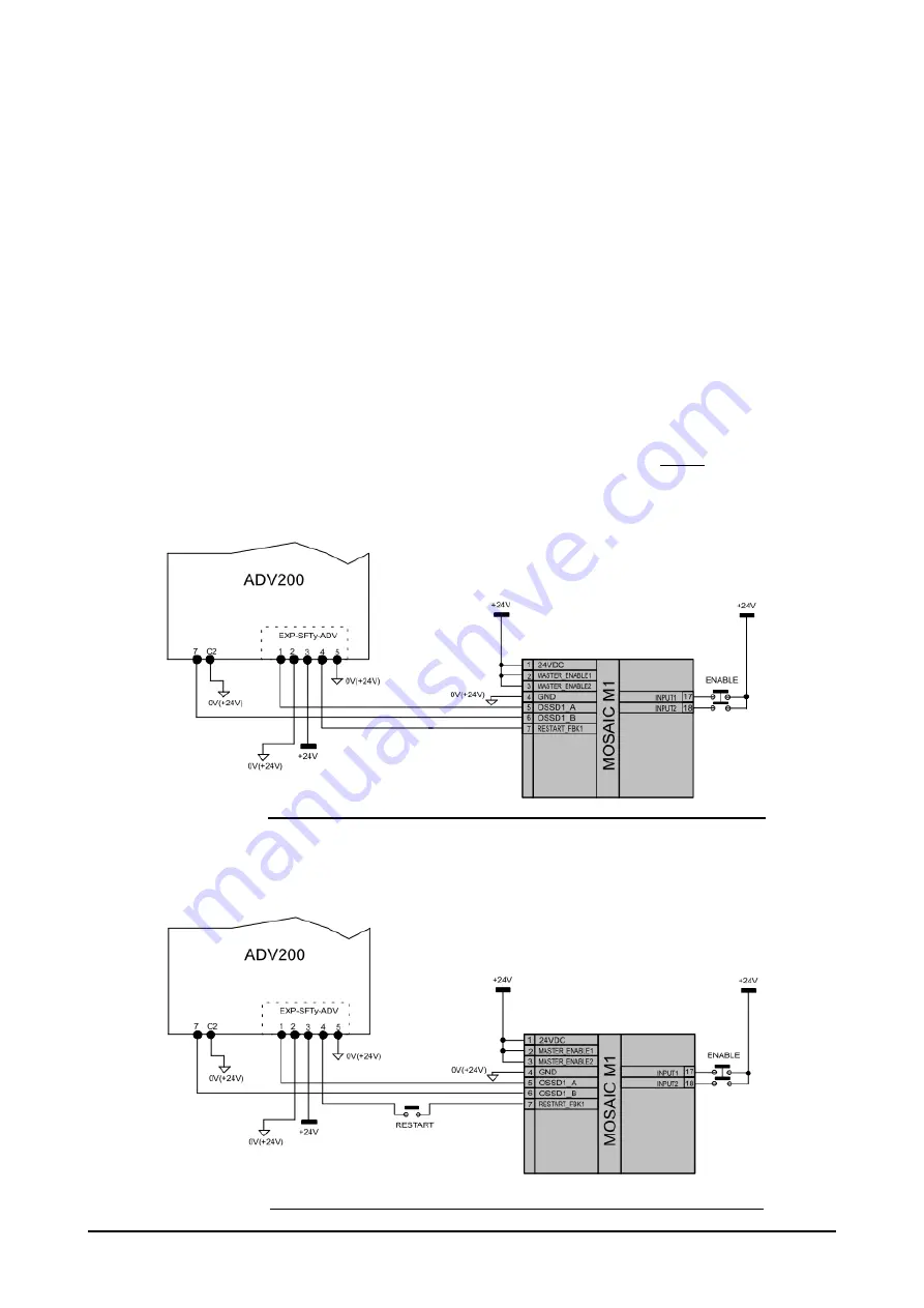
To allow the safety modules to activate the ADV200 STO function and, at the same time, to monitor the STO 
state through inputs with automatic reactivation configuration, the wiring diagram in Figure 4 should be used. 
In this diagram, the outputs of safety module M1 (OSSD1_A, OSSD2_B) control the ADV200 Enable and 
STO Enable inputs. The Feedback output of the STO function is fed to the Restart_Fbk1 input so that the 
module can automatically check the machine status and restart it (if programmed to do so). 


Figure 4. 

Connecting the safety module for activating the STO function with automatic restart. 


Figure 5 shows a diagram that requires/allows a manual restart, using a special safety function button 
(RESTART). 


Figure 5. 

Connecting the safety module for activating the STO function with a manual restart. 

Summary of Contents for ADV200-SI Series

Page 1: ...ADV200 SI with External safety modules English User manual 1S9SFTYEN ...

Page 2: ...anual Safety manual code 1S5F94 EN Thank you for choosing this Gefran product We will be glad to receive any possible information which could help us improve this manual The e mail address is the following techdoc gefran com Before using the product read the safety instruction section carefully Keep the manual in a safe place and available to engineering and installation personnel during the produ...

Page 3: ...ecautions 6 2 1 Symbols used in the manual 6 2 2 Safety Requirements 6 3 Installation and use of safety functions 7 4 Wiring and Installation 8 4 1 Encoder wiring 8 4 2 STO Wiring 10 5 Use and Integration 11 5 1 STO Function 11 5 2 SLS Function 11 5 3 SDI Function 12 5 4 SS1 Function 12 6 SIL levels provided by safety functions 13 ...

Page 4: ... 1100086 X MV2H Safety module MOSAIC HTL Expansion Unit code 1100074 X Mosaic Safety Designer 1 Software for Mosaic safety modules configuration testing and reporting X CSU USB cable USB cable for PC connection code 11100062 X MSC Connector 2 Rear connector for installing an MV2S Module and connecting to M1 cod 11100061 X ADV200 encoder card 3 EXP DE I1R1F1 ADV TTL HTL digital incremental encoder ...

Page 5: ...ing temperature 10 to 55 C Dimensions HxWxD 99 x 22 5 x 114 mm Mounting On an omega type rail in accordance with EN 50022 35 Installation environment Protection level IP54 min Rated voltage 24V DC Dissipated power 3W max Conformity CE cUL TÜV Safety level SIL 3 SILCL 3 PL e Cat 4 Type 4 For all safety modules technical information including dimensions mounting specifications software etc please re...

Page 6: ...applications Indicates an essential or important procedure condition or statement Indique un mode d utilisation de procédure et de condition d exploitation essentiels ou importants 2 2 Safety Requirements Drive integrated safety functions should not be viewed as functions meant for a single device and isolated from the device surrounding context but rather as functions run by one or more component...

Page 7: ...nctions This manual provides information and help for phases 3 and 4 as it is the task and responsibility of the machine manufacturer to design and integrate all safety functions Specifically Paragraphs 4 1 and 4 2 provide the necessary guidelines on how to wire the ADV200 SI device with the safety modules and how to use them for running the basic functions STO SS1 SLS SDI The basic security funct...

Page 8: ... in its special slot EXP SFTy ADV or integrated in the INT P ADV power card sizes 71600 from L HW version For more details see the ADV200 QS manual cod 1S9H49 and the STO safety function manual code 1S5F94 Safety manual EN Figure 1 ADV200 slot diagram for optional cards 4 1 Encoder wiring Motor speed data is required for many safety functions to run namely the following SLS Safe Limited Speed SDI ...

Page 9: ...cond safety module channel to complete the safety network Figure 2 Encoder cable wiring diagram for implementing safety functions With regard to connecting repeated signals to the safety module please see the user manuals for the ReeR M1 MVxS or MVxTB modules Of particular importance is the wiring diagram for TTL signals considering repeated signals as encoder source see Figure 3 In Figure 3 it is...

Page 10: ...5 4 Indeed all safety functions in cases when work interruption is called for require the activation of the Safe Torque Off STO function as a means for machine shutdown or return to safe operation To allow the safety modules to activate the ADV200 STO function and at the same time to monitor the STO state through inputs with automatic reactivation configuration the wiring diagram in Figure 4 shoul...

Page 11: ...arm Configuration and detection methods related to the condition of an exceeded speed limit are described in the safety module manual Upon detecting an exceeded speed limit condition the safety module activates the ADV200 integrated STO function In order to comply with the functional specifications the safety module response times should be added to those of the STO function as described in the Sa...

Page 12: ...S1 function brakes the motor along a quick stop ramp then activates the ADV200 STO function The safety module SS1 function is configured in the best and most responsive way to meet the requirements of the system it controls The SS1 function is generally designed to ensure that after a certain time Tdelay following a request to activate the SS1 function the ADV200 integrated STO function is activat...

Page 13: ... to STO function reliability listed in the 1S5F94 Safety manual EN as well as data related to the encoder signal repetition reliability should be taken into consideration Regarding the latter component the following factors should be considered as well 1 Signal repetition is purely an invariant hardware function Thus its functioning is not affected by other factors or operations Each potential int...

Page 14: ...t Winwick Quay Warrington WA2 8QP Ph 44 0 8452 604555 Fax 44 0 8452 604556 sales gefran co uk GEFRAN INDIA Survey No 191 A 1 Chinchwad Station Road Chinchwad Pune 411033 Maharashtra Ph 91 20 6614 6500 Fax 91 20 6614 6501 gefran india gefran in SENSORMATE AG Steigweg 8 CH 8355 Aadorf Switzerland Ph 41 0 52 2421818 Fax 41 0 52 3661884 http www sensormate ch GEFRAN MIDDLE EAST ELEKTRIK VE ELEKTRONIK ...

Reviews: