


99
10
45
45
48
70
70
63
48
For correct and safe
installation, observe the
warnings contained in
this manual.
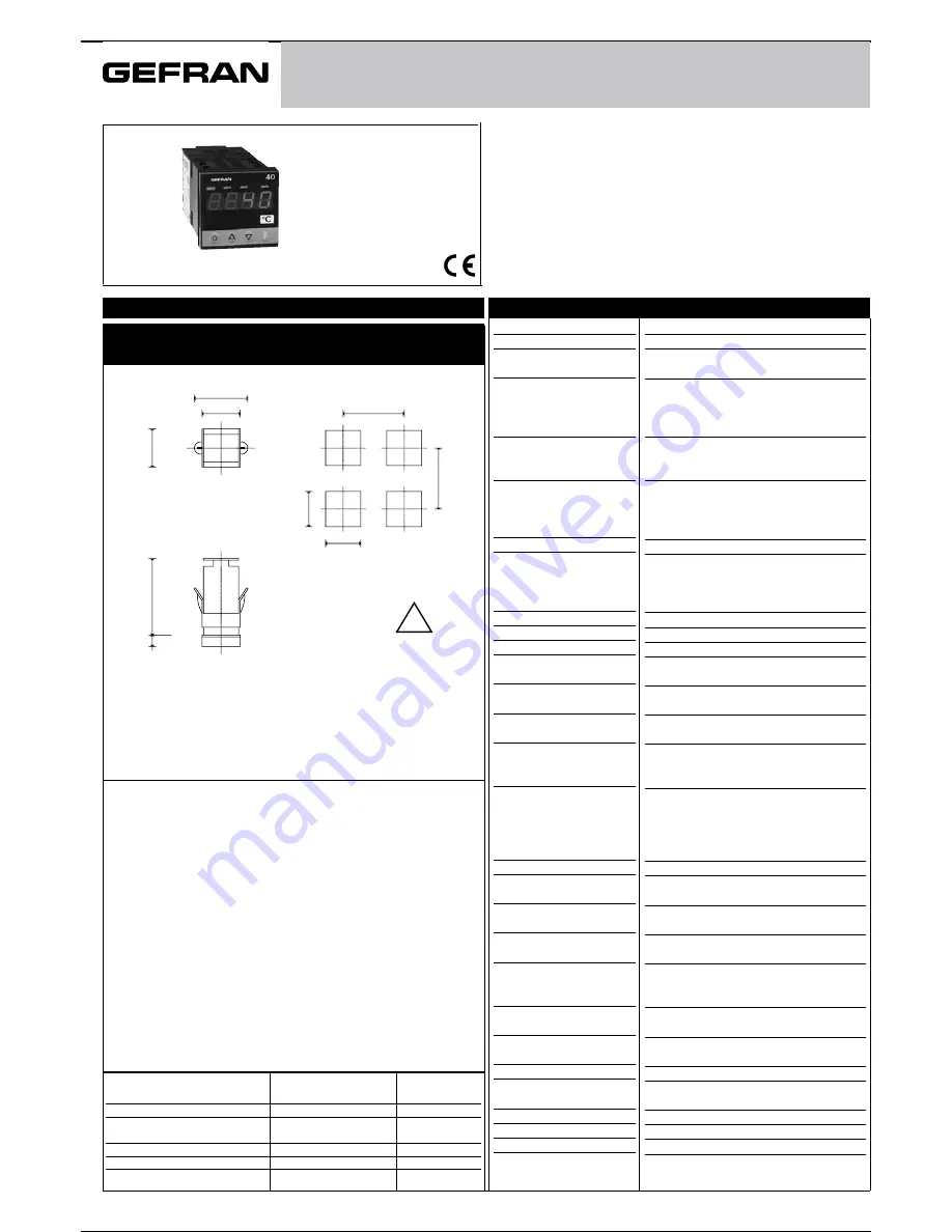
1 • INSTALLATION
• Dimensions and cut-out; panel mounting
Panel mounting
:
Fix the device with the bracket provided before making any electrical
connections.
To mount two or more devices side by side, use the cut-out dimensions
shown above.
CE MARKING
:
The instrument conforms to the European Directives
2004/108/CE and 2006/95/CE with reference to the generic standards:
EN 61000-6-2 (immunity in industrial environment) EN 61000-6-3 (emission
in residential environment) EN 61010-1 (safety)
MAINTENANCE
:
Repairs must be done out only by trained and
specialized personnel. Cut power to the device before accessing
internal parts.
Do not clean the case with hydrocarbon-based solvents (Petrol,
Trichlorethylene, etc.). Use of these solvents can reduce the
mechanical reliability of the device. Use a cloth dampened in ethyl
alcohol or water to clean the external plastic case.
SERVICE
:
GEFRAN has a service department. The warranty excludes
defects caused by any use not conforming to these instruction.
2 • TECHNICAL SPECIFICATIONS
FUNCTION
CABLE TYPE
LENGTH
USED
TC input probe
0,8 mm
2
compensated
5 mt
“PT100” input probe
1 mm
2
3 mt
Power supply cable
1 mm
2
1 mt
Relay output wires
1 mm
2
3,5 mt
Serial connection wire
0,35 mm
2
3,5 mt
EMC conformity has been tested with the following connections
!
40T 48
TEMPERATURE INDICATOR - ALARM UNIT WITH CONFIGURABLE INPUT
SOFTWARE VERSION 3.2x
(includes R77 and R98 versions)
code 81642H / Edition 15 - 11-2013
INSTALLATION and
OPERATION MANUAL
Display
Keys
Accuracy
Resolution
(
function of settable sample
time
)
Main input
TC Type
Thermocouples (ITS90)
Cold junction error
RTD Type (scale configurable
within indicated range, with or
without decimal point, ITS90)
Max. RTD line resistance
PTC Type/ NTC Type
Max. non-linearity error
°C / °F selection
Linear scale ranges
Logic input
Function of logic input
Alarms
(Trip points)
Alarm
masking
Relay contacyt
Logic output
Triac output
Fault settings
(option)
Transmitter / Sensor
Power Supply
(option)
Analog
retransmission
Power supply
(switching)
Faceplate protection
Working / Storage
temperatures
Relative humidity
Environmental conditions of use
Installation
Weight
4 digit red digit height 10mm
3 mechanical keys (Raise, Lower, F)
0.2% f.s. at 25°C ambient temperature,
ts =120msec
120msec, >14bit-16000 points
60msec, >14bit-16000 points (only for linear inputs)
30msec, >13bit - 8000 points (only for linear inputs)
15msec, >12bit - 4000 points (only for linear inputs)
TC, RTD, PTC, NTC
60mV, 1V Ri ≥ 1MΩ, 5V, 10V, Ri ≥10KΩ
20mA, Ri = 50Ω. adjustable digital filter
J, K, R, S, T, B, E, N
(IEC 584-1, CEI EN 60584-1, 60584-2)
L GOST, U, G, D, C. Custom linearization
available on request
0,1° / °C
DIN 43760 (PT100), JPT100
20Ω
990Ω, 25°C / 1KΩ, 25°C
See tP parameter
Faceplate configurable
-1999...9999 Configurable decimal point
position, possible 32 segment linearization
24V, 5mA (Ri = 47KΩ) 1500 V isolation or
voltage-free contact
configurable to reset memory latch, hold, flash,
zero, select max./ min. peak, peak-peak value
Maximum of three configurable alarms:
absolute, deviation, symmetrical deviation.
Adjustable hysteresis
- exclude on power-up
- latch reset from key and/or external contact
- insert delay filter
(DON, DBI, DOF, DPO)
- set minimum intervention time
NO (NC) 5A, 250Vac / 30Vdc
24Vdc, Rout = 500Ω (10V/20mA)
limitation to 30mA
20...240Vac ±10%, 1A max. Snubberless,
inductive and resistive load I
2
t = 128A
2
S
Alarm states can be configured in probe fault
condition
24V ±10%, 50mA
15V for transmitter, max. 50mA
1,2V for potentiometer > 100Ω
10V / 20mA on max. 500Ω resolution 12 bits
(standard) 100...240Vac/dc ±10%, 50/60Hz, 8VA
(optional) 11...27Vac/dc ±10%, 50/60Hz,8VA
IP65
0...50°C / -20...70°C
20...85% Ur non-condensing
for internal use only, altitude up to 2000m
Panel mounting, extractable from front
160 g
1
81642H_MHW_40T48_11-2013_ENG
1 / 18