


Virtual EDID Programming Procedure
If an EDID
is not required
by the DVI source, then EDID programming will not be
necessary. EDID programming
is
required
if the maximum resolution of the
display does not support 1920 x 1200 (WUXGA).
1.
Power on the DVI display.
2.
Connect the 5V DC power supply to the power receptacle of the Sender unit.
Make sure that the Power LED is ON and that the Status LED is blinking
slowly.
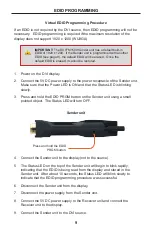
3.
Press and hold the EDID PRGM button on the Sender unit using a small
pointed object. The Status LED will turn OFF.
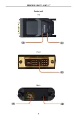
Sender unit
4.
Connect the Sender unit to the display (not to the source).
5.
The Status LED on the top of the Sender unit will begin to blink rapidly,
indicating that the EDID is being read from the display and stored in the
Sender unit. After about 10 seconds, the Status LED will blink slowly to
indicate that the EDID programming procedure was successful.
6.
Disconnect the Sender unit from the display.
7.
Disconnect the power supply from the Sender unit.
8.
Connect the 5V DC power supply to the Receiver unit and connect the
Receiver unit to the display.
9.
Connect the Sender unit to the DVI source.
9
EDID PROGRAMMING
IMPORTANT:
The DVI FM1500 Sender unit has a default built-in
EDID of 1920 x 1200. If the Sender unit is programmed with another
EDID (see page 9), the default EDID will be erased. Once the
default EDID is erased, it cannot be restored.
Press and hold the EDID
PRGM button.