background image


domestic appliances, home automation, smart socket and lamp, industrial wireless 
control system, sensor networks, wearables, wireless position sensing devices, etc.   

1.5


Operating Environment 

1.6


Operating requirements 

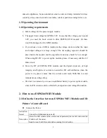
a.


Stable voltage for the power supply module 

b.


The upper limit voltage for GPIO is 3.6V. In case that the voltage goes beyond 
3.6V,  you  need  the  buck  circuit  to  drive  ESP8266  WiFi  module.  Or  there 
would be damages for the GPIO interface.   

c.


If  you choose to use  LDO to transform the voltage, make surethat the input 
and  output  voltages  are  large  enough.  The  decoupling  capacitor  should  be 
place beside the module and the equivalent resistance should be low enough. 
When using DC-DC to power up the module, please, if necessary, add the LC 
filter circuit.   

d.


Since  the  RF  of  ESP8266  WiFi  module  and  the  digital  circuit  are  of  high 
integrity,  and  high-level  current  is  needed  for  FR  self-calibration  when  the 
power  is  on,  please  ensure  that  the  current  could  reach  5000  Ma  to  avoid 
instantaneous voltage drop. 

e.


We don’t recommend you to use un-calibrated battery to power up the module, 
since the FR circuit would be affected by temperature and voltage fluctuation.   


2.


How to use ESP8266 WiFi Module 

2.1


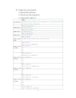
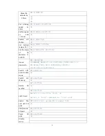
Define the Interface between ESP8266 WiFi Module and 3D 

Printer’s Control Board 


Connect the Server 

Instruction 
format 

 
Connect to srd;devicename;serverIP; 

 
Description 

Inform the WiFi module of the user name and password, the router’s name and the 
IP address of the server.   
Need to reset the WiFi module before sending this instruction. 

Summary of Contents for ESP8266

Page 1: ...equirements 3 2 How to use ESP8266 WiFi Module 3 2 1 Define the Interface between ESP8266 WiFi Module and 3D Printer s Control Board 3 2 2 Define the Interactive Interface between ESP8266 WiFi module and the Server 7 2 3 Define the Interactive Interface between ESP8266 WiFi Module and the mobile Config mode 8 2 4 The Interface between Database and the Console 9 2 5 Define the Interface for Uploadi...

Page 2: ...he microcontroller and send instructions to it ESP8266 WiFi module works as the network interface between 3D printer and mobile devices This WiFi module adhering to the 802 11 network protocol supports the communication between 3D printer and the Geeetech self developed 3D printing App EasyPrint 3D In addition other network endpoints based on the 802 11 network protocol could be compatible with th...

Page 3: ... could communicate with the microcontroller in a convenient way Figure 2 Interface Definition The pin assignments as shown in Figure 1 1 Pin Name Type Function 1 GND P Ground wire 2 CHIP_EN I O Chip Enable Terminal The chip works normally at the high level and closes at the low level with low current 3 RST I O External reset signal works normally at low level 4 RXD I O The RX pin of UART the TX pi...

Page 4: ...nough When using DC DC to power up the module please if necessary add the LC filter circuit d Since the RF of ESP8266 WiFi module and the digital circuit are of high integrity and high level current is needed for FR self calibration when the power is on please ensure that the current could reach 5000 Ma to avoid instantaneous voltage drop e We don t recommend you to use un calibrated battery to po...

Page 5: ...e transmitted one by one Transmit one data package Instruction format xxxxxxxx n Description Xxxxxxxx as the content n as the end signal WiFi module regards xxxxxx as one data package The Network Disconnection Situation When the network is disconnected in case of weak WiFi signal or abnormal logout WiFi module will send one instruction to the control board every 3 seconds The instruction is as fol...

Page 6: ...ome Y axis N80 G28 Y0 98 Y 160 000 ok Home Z axis N81 G28 Z0 96 Z 157 000 ok Home all the axes N82 G28 41 X 280 000 Y 160 000 Z 157 000 ok Move X axis by 1mm N86 G91 47 N87 G1 X 1 F4800 25 N88 G90 32 ok ok ok Move X axis by 1mm N101 G91 17 N102 G1 X1 F4800 8 N103 G90 18 ok ok ok Move Y axis by 1mm N110 G91 17 N111 G1 Y 1 F4800 38 N112 G90 18 ok ok ok Move Z axis by 1mm N113 G91 18 N114 G1 Z 1 F100...

Page 7: ...0 46 ok Inquire device info N11 M115 22 FIRMWARE_NAME V1 08 PROTOCOL_VERSION V1 0 MACHINE_TYPE D200 EXTRUDER_COUNT 2 UUID 16S1123D2000010 Switch off Enter the idle mode N15 M81 46 ok Switch on Wake up N15 M80 46 ok Delete SD card file N15 M30 46 ok List SD card N15 M20 46 Return to the file list ok Return a end command as list end Select file and start SD print N15 M23 foot gcode file name 46 ok S...

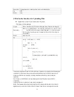
Page 8: ... off line printing etc 2 2Define the Interactive Interface between ESP8266 WiFi module and the Server Log in Instruction format yy_xxx nnnn login Description User name password Users connect the 3D printer with the server Instruction format xxx call yyy Description User xxx visits 3D printer yyy Inform the WiFi module of 3D printer that the data returned will be transferred to user xxx Inquire on ...

Page 9: ...age 3D gcode image test jpg refers to the folder the files Upload a given file from the server to the 3D printer Instruction format xxx server send file filename Description User xxx requests to send the file whose path and name are filename to user yyy 3D printer Regular report to the mobile App about the uploading progress Instruction format server send file progress yyy 10 filename Description ...

Page 10: ...name Administrator Administrator is defined according to the user format Administrator obtains the detailed user info list Format user form Description To obtain the detailed user info list administrator needs to log in at first eg user form Return Format User word friend n eg Administrator adds user name and password Format name word friend Description Administrator adds user name and password Re...

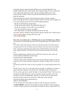
Page 11: ...ushort crc16 byte d intlen byte b 0 ushortcrc 0xff00 inti j for i 0 i len i for j 0 j 8 j b byte d i j 0x80 crc 0x8000 8 crc 1 if b 0 crc 0x1021 crc ushort crc return crc This device complies with part 15 of the FCC Rules Operation is subject to the following two conditions 1 this device may not cause harmful interference and 2 this device must accept any interference received including interferen...

Page 12: ...edures Referring to the multi transmitter policy multiple transmitter s and module s can be operated simultaneously without C2P 3 For all products market in US OEM has to limit the operation channels in CH1 to CH11 for 2 4G band by supplied firmware programming tool OEM shall not supply any tool or info to the end user regarding to Regulatory Domain change USERS MANUAL OF THE END PRODUCT In the us...

Page 13: ... Operation is subject to the following two conditions 1 this device may not cause harmful interference and 2 this device must accept any interference received including interference that may cause undesired operation ...

Reviews: