background image

How To Install a Laing Heater

Follow instructions below to install a Laing heater on MC-MP Metapacks.

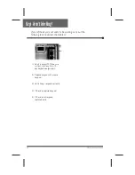
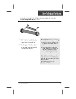
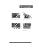
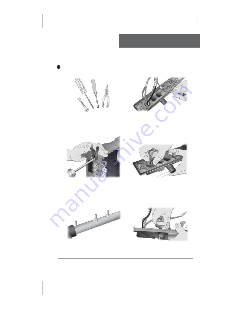
1•  To install a Laing heater on a 


MC-MP Metapack, you will


need pliers, a Phillips screwdriver,


a 11/32" nut driver and a 3/8" open


end wrench.

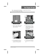
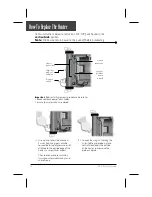
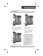
4•  With the heater plate in position,


squeeze the groud cable between


2 nuts (one on top of the other) 


with a wrench.


2•  Install heater top holders on both


upper sides of the pack. These


holders can be adjusted and should


be fixed only after heater has been


placed in its final position.

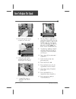
5•  Hand tight heater cable plastic nut


in place.

6•  Do the same with the pressure 


switch.

3•  Slide nylon sleeves into heater 


threaded studs.

73

MC-MP Service Manual

Summary of Contents for MC-MP

Page 1: ...MC MPSPASYSTEMS ServiceManual byGeckoAlliance Visualstep by stepguidetoeasily identify correcttechnicalproblems ...

Page 2: ...TableofContents ...

Page 3: ...detailed information Important Safety Information WARNING Risk of electrical shock All procedures described in this service manual must only be performed by qualified personnel in accordance with the standards applicable in the country of installation and whenever possible with the equipment powered off When connecting the equipment always refer to the wiring diagram affixed to the inside of your ...

Page 4: ...Tools Parts ...

Page 5: ...service box GFCI box and pack terminal block is essential 1 Carry out a visual inspection to check for signs of miswiring Refer to supplied wiring diagrams Call an electrician if necessary Electrical Box GFCI Pack Terminal Block 4 MC MP Service Manual ...

Page 6: ...till tripping Replace GFCI Replace board if GFCI is still tripping There is a problem with the cable Call an electrician Unplug everything including heater and light cord wires Is GFCI still tripping Replace transformer Reconnect one component at a time until GFCI starts to trip Replace defective component Verify Wiring Diagram and reconnect it yes yes no no yes no 5 MC MP Service Manual ...

Page 7: ...re common If breaker is wired properly GFCI trippings may occur when total amount of current drawn by spa exceeds breaker rating This is highly unlikely as each spa pack output is individually fused and fuses will blow before GFCI trips A current leak to ground will also cause GFCI to trip If any of the components is faulty and a leak of more than 5mA occurs GFCI will trip to prevent electrocution...

Page 8: ...Call an electrician 2 If GFCI stops tripping replace GFCI 3 If GFCI trips again replace board Refer to How to Replace the Board section of this manual If GFCI continues to trip even after having replaced the transformer carry out the following tests to correct the problem 7 MC MP Service Manual ...

Page 9: ...re than one pump is on at high speed Position 2 LC The system will not turn heater on if any pump 1 2 or 3 is on at high speed Heater indicator will flash on display indicating that more heat is requested but heater will not be allowed to start Jumper 2 Keypad Configuration Position 1 10 key configuration Position 2 8 key configuration Remove MC MP power box cover to access jumpers See How to Repl...

Page 10: ...LowLevelProgramming 9 MC MP Service Manual ...

Page 11: ...10 MC MP Service Manual ...

Page 12: ...ontinuity on your voltmeter for pressure switch yes no Short pressure switch terminals with a jumper cable Replace pressure switch cable Replace pressure switch cable Remove anything obstructing filter canister or piping Clear any air locks Verify water valves Try to adjust pressure switch Are dots still flashing on keypad display If problem persists replace board yes no Verify pressure switch con...

Page 13: ... following steps are carried out 5 If you do not detect continuity verify if pressure switch cable is properly connected to pressure switch and board 1 Verify if Pump 1 or circulation pump if installed is working If pump is not working right refer to pump section of this manual 2 Make sure jumper is set pro perly for circulation pump 3 If Pump 1 is working properly turn it on by pressing Pump 1 ke...

Page 14: ...n 2 years replace the pressure switch and re calibrate it If installation is recent try readjust ing the pressure switch If this is not possible replace switch Refer to How to Adjust the Pressure Switch section of this manual 8 If the three dots still appear the problem may be either with switch cable or board Remove plastic cover and replace cable 9 Replace board if error condition still persists...

Page 15: ... still persists Refer to How to Replace the Board section of this manual 10 If you have continuity on pressure switch follow these steps Disconnect pressure switch cable for 5 seconds and reconnect it If error condition disappears ad just pressure switch if it is a new installation less than two years or replace it Refer to How to Adjust the Pressure Switch section of this manual 14 MC MP Service ...

Page 16: ...FlashingdotsandLEDFlowChart 15 MC MP Service Manual ...

Page 17: ...pad display shows incorrect temperature 1 Take water temperature with a digital thermometer 2 If keypad display shows correct temperature a Check if heater barrel feels hot If it s hot verify if anything is obstructing the flow of water closed valves or dirty filter b If it s not verify if hi limit probe is properly connected Try to clean probe connector pins Even a small coating of film can cause...

Page 18: ...nected If it is replace probe and reset breaker 3 Replace board if error condition still persists Refer to How to Replace the Board section of this manual 1 Verify if temperature probe is in contact with water and if cold air from the back could be affecting readings Use foam to isolate probe from cold air if that is the problem 17 MC MP Service Manual ...

Page 19: ...18 MC MP Service Manual ...

Page 20: ...ouching water or if cold air from back can affect reading Remove spa cover even during the night Start blower if spa is equipped with one Wait until spa cools down add cold water if needed Pump is overheating water during filter cycle Lower filter cycle duration Replace board Lower set point below actual temperature of water Heater indicator on keypad display should disappear Do you get a 240 VAC ...

Page 21: ...DisplayIsFlashing 20 MC MP Service Manual ...

Page 22: ...ake sure temperature probe is properly connected If it is replace probe 3 Replace board if display is still flashing Refer to How to Replace the Board section of this manual 1 Verify if temperature probe is in contact with water and if cold air from the back could be affecting readings Use foam to isolate probe from cold air if that is the problem 21 MC MP Service Manual ...

Page 23: ...22 MC MP Service Manual ...

Page 24: ...Flow Chart below to identify the problem Replace board if problem persists Check if regulation probe is properly connected Replace probe with a spare and verify if problem is solved If it is replace probe with spare Unplug probe connector and clean pins on the board even a small coating of film may cause a bad connection Reconnect the probe 23 MC MP Service Manual ...

Page 25: ...y out the following steps Power can remain On 1 Verify if regulation probe sensor located in spa is properly connected 3 Reconnect probe If wrong temperature is still displayed replace probe with a spare and place probe head directly in spa water If problem is solved replace probe 4 Replace board if problem persists 2 Disconnect probe connector and clean probe connector pins Even a small coating o...

Page 26: ...if pressure switch cable is properly connected to pressure switch and board There must be adequate water in spa for normal use yes no Is anything limiting flow of water into pipes yes no Is it a new installation less than two years Replace pressure switch Adjust pressure switch Replace board Ensure flow of water through heater and short two pressure switch terminals with a jumper Does FLO error co...

Page 27: ...e heater will automatically shut down when an FLO error condition occurs Power may remain On when the following steps are carried out 4 Verify if pressure switch cable is properly connected to pressure switch and board 1 Verify if pump or circulation pump if present is working If pump is not working right refer to pump or circulation pump section of this manual 2 Make sure jumper setting for circu...

Page 28: ...sure switch and recalibrate it If installation is recent try readjusting the pressure switch If this is not possible replace switch Refer to How to Adjust the Pressure Switch section of this manual 7 If FLO error condition persists the problem may be either with switch cable or board Remove plastic cover and replace cable 8 Replace board if FLO error condition still persists Refer to How to Replac...

Page 29: ...28 MC MP Service Manual ...

Page 30: ...itch cable Does FLO error condition occur when pump is on Adjust pressure switch Is it a new installation less than two years Replace pressure switch cable Replace pressure switch if FLC error condition persists when you start or stop pump Replace pressure switch Replace board yes no yes no First ensure jumper position for circulation pump is set correctly see Jumper Section 29 MC MP Service Manua...

Page 31: ...e switch cable 4 Replace board if FLC error condi tion still persists Refer to How to Replace the Board section of this manual 1 First check to ensure jumper position for circulation pump is set correctly see Jumper Section If not readjust jumper Disconnect pressure switch cable 2 If FLO error condition occurs when pump is started adjust pressure switch if it is a new installation less than two ye...

Page 32: ...red after 98 Prr error status is ignored during first hour after initial power up to allow water to heat to over 35 F Check if regulation probe is properly connected Replace probe with a spare and verify if problem is solved If it is replace probe with spare Unplug probe connector and clean pins on the board even a small coating of film may cause a bad connection Reconnect the probe Pressing any k...

Page 33: ...g any key after each step resets system Power can remain On 1 Verify if regulation probe sensor located in spa is properly connected 3 Reconnect probe If Prr error condition still persists replace probe with a spare and place probe head directly in spa water If problem is solved replace probe 4 Replace board if problem persists 2 Disconnect probe connector and clean probe connector pins Even a sma...

Page 34: ...one Wait until spa cools down add cold water if needed yes no Lower set point below actual temperature of water Heater indicator on keypad display should disappear Do you get a 240 VAC reading between two heater wires on the board yes no Is HL probe properly connected Clean pins reconnect it and reset the breaker Verify if anything is obstructing water flow closed traps or dirty filters If HL OH e...

Page 35: ...ter 2 If reading is below 112 F HL OH error condition should be steady indicating a problem at the hi limit probe and heater level a Check if heater barrel feels hot If it s hot verify if anything is ob structing the flow of water closed valves or dirty filter b If it s not verify if hi limit probe is properly connected Try to clean probe connector pins Even a small coating of film can cause a bad...

Page 36: ...HL OH ErrorCondition 35 MC MP Service Manual ...

Page 37: ...mperature probe is properly connected If it is replace probe and reset breaker 3 Replace board if HL OH error condition still persists Refer to How to Replace the Board section of this manual 1 Verify if temperature probe is in contact with water and if cold air from the back could be affecting readings Use foam to isolate probe from cold air if that is the problem 36 MC MP Service Manual ...

Page 38: ...ndicator is flashing on keypad follow this Troubleshooting Flow Chart to identify the problem Is the water temperature of the spa lower than the desired temperature Do you read 240 VAC to the heater Refer to Spa not heating section yes yes no System works fine no 37 MC MP Service Manual ...

Page 39: ...SmartWinterMode 38 MC MP Service Manual ...

Page 40: ...op of the plug Replace transformer fuse if there is still nothing on the keypad display There is an electrical wiring problem Call an electrician Replace board if problem still persists yes no If nothing seems to work follow Troubleshooting Flow Chart below to identify the problem If nothing still works clean the transformer orange connector pins even a small coating of film may cause a bad connec...

Page 41: ...here is probably a power supply problem Carry out the following tests to identify and correct the problem 3 Measure voltage between line 2 and neutral You should get 120 VAC 4 If you do not get good readings this indicates an electrical wiring problem Call an electrician 2 Measure voltage between line 1 and neutral You should get 120 VAC 40 MC MP Service Manual ...

Page 42: ... tests to correct the problem 3 If nothing works clean transformer orange connector pins Even a small coating of film may cause a bad connection 4 Replace transformer if problem persists 5 If problem is still not solved replace board Refer to How to Replace the Board section 2 Replace transformer fuse if nothing still seems to work Xfo fuse 41 MC MP Service Manual ...

Page 43: ...42 MC MP Service Manual ...

Page 44: ... SpaNotHeating FlowChart 43 MC MP Service Manual ...

Page 45: ...SpaNotHeating 44 MC MP Service Manual ...

Page 46: ...SpaNotHeating 45 MC MP Service Manual ...

Page 47: ...46 MC MP Service Manual ...

Page 48: ...PumpFlowChart 47 MC MP Service Manual ...

Page 49: ...Pump1DoesNotWork 48 MC MP Service Manual ...

Page 50: ...C pump P57 P64 120 VAC pump P48 P64 The reading shoud be 240 VAC for a 240 VAC pump 120 VAC for a 120 VAC pump If Pump1 does not work in any speed carry out the following tests to correct the problem 3 Turn Pump 1 to high speed and measure voltage between white and red wire connectors 240 VAC pump P57 P37 120 VAC pump P48 P37 The reading shoud be 240 VAC for a 240 VAC pump 120 VAC for a 120 VAC pu...

Page 51: ...Pump2DoesNotWork 50 MC MP Service Manual ...

Page 52: ...orking in any speed carry out the following tests to correct the problem 2 If replacing fuse does not correct problem or if Pump 2 works in one of two speeds read voltage on the board for both speeds 3 Turn Pump 2 to high speed and measure voltage between white and red wire connectors 240 VAC pump P58 P22 120 VAC pump P45 P22 The reading shoud be 240 VAC for a 240 VAC pump 120 VAC for a 120 VAC pu...

Page 53: ...52 MC MP Service Manual ...

Page 54: ...BlowerFlowChart 53 MC MP Service Manual ...

Page 55: ...BlowerDoesNotWork 54 MC MP Service Manual ...

Page 56: ...ou still aren t getting a voltage reading Refer to How to Replace the Board section 4 If you do get a good voltage reading check if you can restart blower a few minutes after being turned off Replace blower if it does not start after cool down period 5 If blower does start up after cool down it s possible that it is not drawing in enough air 6 Enlarge the opening to allow more air into blower Blow...

Page 57: ...56 MC MP Service Manual ...

Page 58: ...SpaLightFlowChart 57 MC MP Service Manual ...

Page 59: ...SpaLightDoesNotWork 58 MC MP Service Manual ...

Page 60: ... aren t getting a voltage reading yes yes no no Replace ozonator If the user turns on a pump blower or light during a filter cycle the cycle will be interrupted and will only resume 40 minutes after last active output has been turned off automatically or manually This delay is to prevent excessive ozonator activation During this interval Filter cycle indicator will flash in a different sequence On...

Page 61: ...OzonatorDoesNotWork 60 MC MP Service Manual ...

Page 62: ...CirculationPumpFlowChart 61 MC MP Service Manual ...

Page 63: ...CirculationPumpNotWorking 62 MC MP Service Manual ...

Page 64: ...KeysFlowChart 63 MC MP Service Manual ...

Page 65: ...KeysAren tWorking 64 MC MP Service Manual ...

Page 66: ...HowToReplaceTheBoard 65 MC MP Service Manual ...

Page 67: ...oard plate assembly Note trans former remains attached to board 9 Correctly align replacement board metal plate assembly with original screw holes and reattach to board with 5 screws 10 Now reinsert J J mini connector to pack side 11 Switch transformer from one plate to the other 12 Re connect heater cables 13 Re connect pressure switch and high temperature sensor cables 14 Verify all connections ...

Page 68: ... upwards in no particular order Important Before starting removal procedure be sure to disconnect pack power input cables ensure spa water valves are closed 2 Using a 1 4 wrench to hold steady and a 3 8 wrench to carefully turn loosen nuts securing 2 heater con nectors to top of blue plastic support plate Disengage heater wires Be careful not to damage ceramic by twisting or bending Pressure switc...

Page 69: ...HowToReplaceTheHeater 68 MC MP Service Manual ...

Page 70: ...standard horizontal front bottom position A few helpful hints when reconnecting a Don t turn wing nut too tightly just enough to hold rubber sensor in place b When reconnecting wires from heater to board it is important to use two wrenches to hold nuts steady Any bending or twisting may cause damage to ceramic Note We recommend the use of an adjustable torque wrench 17 lb in to screw the top nut s...

Page 71: ...centrally located on the outside of the heater and remove the probe and plate Pressure switch High limit wing nut and plate Lock nut attaches heater to pack Ground connection Heater connections Important Before starting removal procedure be sure to disconnect pack power input cables ensure spa water valves are closed HowToReplaceTheHeater Follow instructions below to replace an MC MP pack heater i...

Page 72: ...wrench to hold steady and 3 8 wrench to loosen nuts to discon nect 2 heater wire connections Be careful not to damage ceramic by twisting or bending A few helpful hints when reconnecting a Don t turn wing nut too tightly just enough to hold high temperature sensor in place b When reconnecting wires from heater to board it is important to use two wrenches to hold nuts steady Any bending or twisting...

Page 73: ...uctions as for the front horizontal heater position shown on previous pages The main difference is in the position of the blue plastic support plate which sits on the top of the heater in the front position but is positioned sideways at the bottom of the pack in the back horizontal position Back horizontal heater position Pressure switch Heater connectors nuts High limit wing nut plate Heater lock...

Page 74: ...With the heater plate in position squeeze the groud cable between 2 nuts one on top of the other with a wrench 2 Install heater top holders on both upper sides of the pack These holders can be adjusted and should be fixed only after heater has been placed in its final position 5 Hand tight heater cable plastic nut in place 6 Do the same with the pressure switch 3 Slide nylon sleeves into heater th...

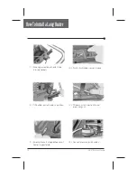
Page 75: ... top holders 10 Push hi limit rubber sensor in place 8 Tilt bottom part of heater in position 11 Tilt down hi limit plastic latch and screw wing nut 9 Screw plate nuts at opposite ends of heater support plate 12 Connect pressure switch cables 74 MC MP Service Manual ...
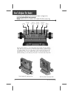
Page 76: ...tallaLaingHeater 13 Connect ground cable to board 16 Verify heater plate connections and place pack cover 14 Connect heater cables to board 15 Adjust top holders in their final position 75 MC MP Service Manual ...
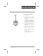
Page 77: ...r full turn 4 Turn Pump 1 on at low speed and wait a few minutes If 3 flashing dots do not appear you have adjusted the pressure switch successfully If 3 flashing dots appear decrease pressure switch setting by turning counter clockwise until voltmeter starts beeping there is continuity Then decrease another 1 4 of turn Turn pump off The 3 flashing dots should not appear restart procedure if 3 fla...

Page 78: ...ng by very slowly turning adjustment screw clockwise until three flashing dots disappear then another full turn 4 Turn pump on at low speed for 30 seconds there should be no flashing dots on display 5 Turn pump off and wait 30 seconds You should not see the three flashing dots 6 If you see an error restart the adjust ment procedure If you are not able to adjust the pres sure switch change it 77 MC...

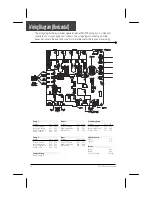
Page 79: ...P49 P49 Ozone Voltage 120 v 240 v Green Ground P73 P73 Black High Speed P30 P30 White Com P46 P60 Circulation Pump Voltage 120 v 240 v Green Ground P74 P74 Black High Speed P36 P36 White Com P41 P54 Light Connector Light 1 P14 Light 2 P13 Heater Black 1 P63 Black 2 P44 Green Ground Ground The wiring diagram below provides a general idea of MC MP wiring but it is important to note that it may not a...

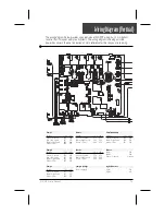
Page 80: ...ne Voltage 120 v 240 v Green Ground P73 P73 Black High Speed P30 P30 White Com P46 P60 Jumper Settings Refer to page 8 Circulation Pump Voltage 120 v 240 v Green Ground P74 P74 Black High Speed P36 P36 White Com P41 P54 Heater Black 1 P63 Black 2 P44 Green Ground Ground Light Connector Light 1 P14 Light 2 P13 The wiring diagram below provides a general idea of MC MP wiring but it is important to n...

Page 81: ...ProfessionalRepairKit Allyouneedinonecase ...

Page 82: ...Corona CA 92883 USA 951 667 2000 www geckoalliance com COMPLETESERVICE GUIDEWITHSTEP BY STEP INSTRUCTIONSON GFCITroubleshooting JumperSelection Understanding Correcting ErrorConditions SystemMalfunctions PartReplacement Instructions More Clearly Advanced Spa Systems 3 85 7089 9919 100435 Rev 04 07 ...

Reviews: