


14
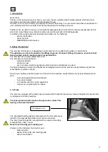
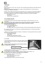
3.5. Operating
The winches are suitable for manual operation only.
For the load to be hoisted, turn the crank clockwise.
For the load to be lowered, turn the crank anticlockwise.
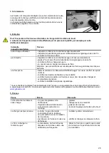
4. Maintenance
The winch must be unloaded for inspection and maintenance tasks.
Inspection and maintenance tasks must be performed by skilled personnel, e.g. via your Gebuwin
dealer.
Inspection/ Maintenance
interval
Tasks
Before each use
-
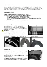
visually check cable and loading hook
-
check amount of grease* on the worm wheel gearing
-
check the brake function
Per quarter
-
visually check cable and loading hook for any fracture
-
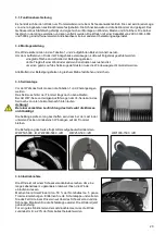
grease the worm - worm wheel gearing
-
check the load pressure brake for wear and tear
Replace the brake discs as needed
Be careful: Do not get any grease on the brake discs or preceding
surfaces
Annually
-
check the cable according to DIN 15020 pg. 2 for wear and tear; also
test and maintain the minimum breaking force.
-
check the tightness of the mounting bolts
-
check all the winch parts for wear and tear; replace where necessary;
grease where needed.
-
check the type identity sticker for clarity
* Texaco “Texclad premium 2” is recommended by us for the worm - worm wheel gearing (or equivalent).
Orders can be placed through your Gebuwin dealer or on the website:
5. Troubleshooting
Trouble/Malfunction
Cause
Solution
The unloaded winch rotates
heavily
-
no grease on the gearing
-
dirt on the gearing
-
during mounting the winch has
pulled askew
-
apply grease
-
clean with a detergent and re-
grease
-
level the mounting surface and re-
mount the winch
The load cannot be held
-
the cable has been incorrectly
wound round the drum which
means the crank turning
direction is incorrect
-
the brake discs are either worn
down or faulty
-
wind the cable correctly around
the drum
-
check and/or renew the brake
discs
The load pressure brake does
not function
-
braking mechanism and/or discs
are jammed due to infrequent
use
-
loosen the brake by hitting the
crank in the correct turning
direction with the flat of the hand
Summary of Contents for WW1000 D/Ex Series
Page 2: ...1...