


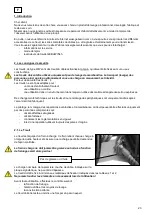


12
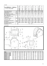
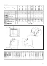
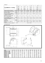
Chart 2
Type WW2000 >> 5000 kg
(..)= sec. drive shaft
WW
2
0
0
0
.
./
D
WW
2
0
0
0
.
./
G
D
WW
2
0
0
0
.
./
2
D
WW3
0
0
0
.
./
D
WW
3
0
0
0
.
./
G
D
WW
3
0
0
0
.
./
2
D
WW
4
0
0
0
.
./
D
WW
4
0
0
0
.
./
G
D
WW
4
0
0
0
.
./
2
D
WW
5
0
0
0
.
./
D
WW
5
0
0
0
.
./
G
D
WW
5
0
0
0
.
./
2
D
Hoisting load first layer
Kg
2000
2x1000
3000
2x1500
4000
2x2000
5000
2x2500
Hoisting load last layer
Kg
1129
2x565
1861
2x930
2390
2x1195
3165
2x1583
Cable diameter
mm
13
9
16
10
16
13
20
16
Min. breaking force of cable
kN
106
51
161
63
179
106
252
161
Max. Cable storage calculated per
cable compartment
m
46
51
52
68
52
42
40
27
Max. cable layers per cable
compartment
6
10
6
10
6
8
5
6
Crank force first layer
daN
22(12)
22(12)
28(17)
28(17)
37(14)
37(14)
52(18)
52(18)
Transmission ratio
1:38
(1:76)
1:38
(1:76)
1:52
(1:104)
1:52
(1:104)
1:60
(1:180)
1:60
(1:180)
1:60
(1:180)
1:60
(1:180)
Hoisting height per crank rev.
mm
12(6)
12(6)
11(6)
11(6)
11(4)
11(4)
12(4)
12(4)
Own weight
Kg
60
62
78
80
80
82
117
119
Wall fastening, class 8.8 bolts
4xM20
4xM20
4xM20
4xM20
4xM20
4xM20
4xM20
4xM20
Permitted environment
temperature
-10°C / +50°C
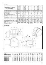
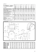
Dimensions
Type
A
B
C
D
G
H
J
K
L
M
N
O
P
R
S
WW250 ../D (GD)
238 145 100 192 106 102
48
14
160 191
15
354 280 171 130
WW500 ../D (GD)
269 160 115 223 107 131
70
14
190 221
15
384 325 192 130
WW1000 ../D (GD)
302 195 141 254 110 160 102
17
240 266
15
429 350 264 130
WW1500 ../D (GD)
302 250 178 254 111 160 102
17
240 278
15
441 350 306 130
WW250 ../2D
238 145 100 192 106
52
48
14
160 191
15
354 280 171 130
WW500 ../2D
269 160 115 223 107
63
70
14
190 221
15
384 325 192 130
WW1000 ../2D
302 195 141 254 110
78
102
17
240 266
15
429 350 264 130
WW1500 ../2D
302 250 178 254 111
78
102
17
240 278
15
441 350 306 130
Type
A
B
C
D
G
H
J
K
L
M
N
P
R
S
WW2000 ../D (GD)
410
310
196
360
137
176
133
25
312
383
45
380
420 220
WW3000 ../D (GD)
436
365
251
386
137
204
165
25
376
443
47
380
527 220
WW4000 ../D (GD)
436
365
251
386
137
204
165
25
376
443
47
380
527 220
WW5000 ../D (GD)
436
425
316
386
137
200
219
25
437
495
60
380
604 220
WW2000 ../2D
410
310
196
360
137
85
133
25
312
382
45
380
420 220
WW3000 ../2D
436
365
251
386
137
100
165
25
376
442
47
380
527 220
WW4000 ../2D
436
365
251
386
137
100
165
25
376
442
47
380
527 220
WW5000 ../2D
436
460
316
386
137
98
219
25
437
494
60
380
604 220
Summary of Contents for WW1000 D/Ex Series
Page 2: ...1...