


GEAX
s.r.l.
Chapter 5
CONTROLS
6
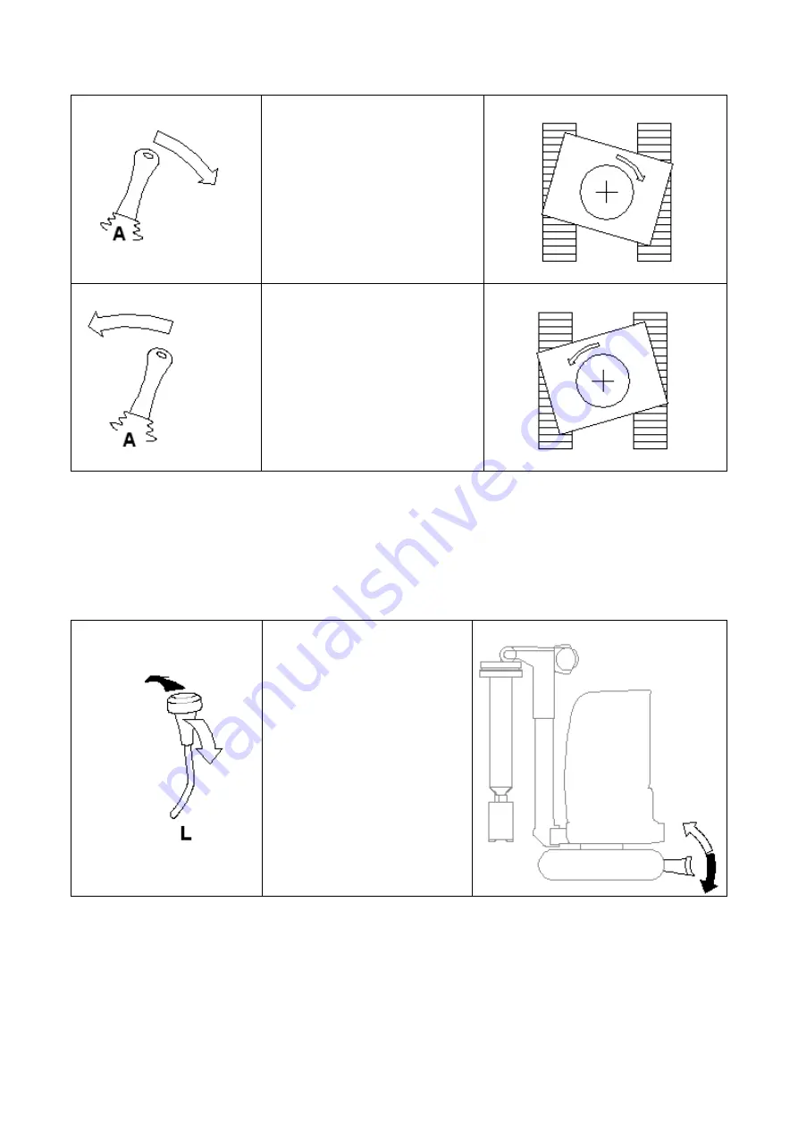
Move joystick
A
to the right
(towards the seat) to make
the turret turn clockwise.
Move joystick
A
to the left to
make the turret turn
counterclockwise.
5.1.8
Dozer blade and extending undercarriage controls
Lever L has the double function of positioning (lift-down) the blade and to vary
(enlarge-tighten) the undercarriage. A separate switch selects the function
(see JCB manual).
Switch position: BLADE
• Pushing the lever L, the
blade is lowered (black
arrow);
• Pulling back the lever L,
the blade rises (white
arrow).


