


02
05
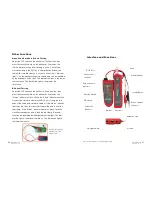
Telephone Cable Tracing Function
1. Directly insert telephone wire with RJ11 plug into RJ11 port of
emitter (
Note: Do NOT put live telephone cable into RJ45 port, doing
so may result in burning of testing device.)
2. Push DIP switch on emitter to “SCAN” position. Wire locator
indicator “STATUS” will flash, which indicates normal operation of
emitter.
3. While using the probe, press the inching button on receiver to find
target wire.
4. During testing, to switch testing over to dual-tone, press “Switch”
button.
EX
AM
PL
E
1
Fi
nd
in
g
wi
re
o
n
sw
itc
h
Connect emitter with
telephone line to be located
Trace cable with receiver at
the other end
Connect emitter with
telephone line to be located
Trace cable with receiver at
the other end
EX
AM
PL
E
2
Fi
nd
in
g
wi
re
o
n
pa
tc
h
pa
ne
l
Network Wire Collation Function
1. Insert the two ends of a networking cable into the RJ45 ports of
the emitter and receiver.
2. Push function switch button on emitter to the position of “TEST”,
testing indicator “VERIFY” will flash which indicates that the emitter
is working properly.
3. Short circuit, breaking circuit, open circuit or wires crossing
indicated on device.
4. During testing, pressing on the Switch button will toggle between
fast and slow levels.
Supports direct wire collation
of operating switch
Quickly test open circuit/short circuit
and wire crossing through status
indicators.
Replace standard
cable testers
Note
: The equipment is prohibited to be used on heavy-current wires.