

06
01
* Color of actual product may be different than depicted
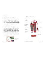
Interface and Functions
RJ45 Port
Wire Locator
Indicator
Function Switch
DIP Switch
Verification
Indicator
Spotlight Switch
Emitter
Receiver
Earphone Jack
Volume
Probe
Signal Indicator
Inching Button
Wire Sequence
Indicator
Wire Sequence
Indicator
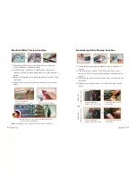
Other Functions
Open Circuit or Short Circuit Testing
Adjust the DIP switch on the emitter to “Test” position, then
press the function switch on the emitter for 2 seconds, the
“Verify” indicator will go from flashing to solid. Connect the
crocodile clamp to the RJ11 port, clamp the two ends of the
cable with crocodile clamps, in case of a short circuit. Indicator
light “1” on the emitter will light up. Impedance can be identified
by the brightness of the light. The dimmer the light is, the lower
the resistance. The darker the light is, the greater the
resistance.
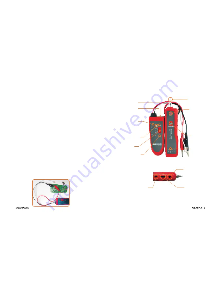
DC Level Testing
Adjust the DIP switch on the emitter to “Scan” position, then
press the function switch on the emitter for 2 seconds, the
“Status” indicator will turn off and the “Verify” indicator will flash.
Connect the crocodile clamp to the RJ11 port, clamp the two
ends of the cable with crocodile clamps. If the “Status” indicator
light turns red, then this classifies the positive pole is from the
red clamp. If the “Status” indicator light turns green, then this
classifies the negative pole is with the red clamp. Electrical
level can be identified by the brightness of the light. The dim-
mer the light is, the higher the level is. The darker the light is,
the lower the level is.
Testing for positive and
negative pole of DC
electrical level


