background image

3

96

19

4-

05

.2

01

6-

Gb

Identification of safety instructions

General safety instructions

DANGER!


Indicates a dangerous situation which, if not avoided,  
will cause immediate fatal or serious injury.

DANGER!


Indicates a dangerous situation which by electrical current, if not avoided,  
will cause immediate fatal or serious injury.

WARNING!  

 Indicates a dangerous situation which, if not avoided,  
may cause fatal or serious injury.

CAUTION!


 Indicates a dangerous situation which, if not avoided,  
may cause fairly severe or minor injury.

ATTENTION!


 Indicates a situation which, if not avoided,  
may cause property damage.

INFO! 

Important information / tips on simplifying work.

Safety instructions

Target group of these instructions

•  Work on the compressor may only be carried out by persons whose technical training, skills and expe-
     rience along with their knowledge of pertinent regulations and documentation means that they are capa- 
     ble of assessing the work to be carried out and detecting any possible dangers
•  Specialist can mean a refrigeration technician for example. Note that electrical work may only be carried  
     out by a qualified electrician. Alternatively, on a country-specific basis, persons who have undergone elec-
     trotechnical instruction and who have proof of their qualification are also permitted to carry out the work.

1 I Safety

WARNING! 

•  

Refrigerating compressors are pressurised machines and therefore require particular  
caution and care in handling.


•  

Risk of burns! Depending on the operating conditions, surface temperatures of over 60 °C  
on the pressure side or below 0 °C on the suction side can be reached.


•  

The maximum permissible overpressure must not be exceeded,  
even for testing purposes.

DANGER!  Risk of electric shock


• 

Before you carry out any repair work, disconnect the compressor from the electricity network.


• 

Turn the main switch to "O" (OFF).


• 

Secure the main switch against an unauthorised restart.

Summary of Contents for HG34P Series

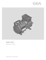
Page 1: ...1 96194 05 2016 Gb Maintenance manual HG34P I HG34e engineering for a better world...

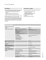
Page 2: ...nstructions Liability and warranty Manufacturer s liability and warranty are excluded if Alterations and functional modifications have been carried out No original replacement parts have been used Con...

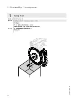
Page 3: ...rtinent regulations and documentation means that they are capa ble of assessing the work to be carried out and detecting any possible dangers Specialist can mean a refrigeration technician for example...

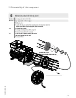
Page 4: ...erature Oil problems Abnormal compressor running noise Compressor stand still Compressor does not start Problem Possible cause Remedy Control circuit is interrupted Main or control fuse is switched of...

Page 5: ...t refrigerant to normal filling Non condensible gases in refrigerant Extract refrigerant and evacuate the refrigeration plant refill refrigerant Cutoff through heatprotection thermostat accessory Disc...

Page 6: ...valve if necessary Lack of compressor capacity Check the function of the compressor by evacuating to vacuum Check function of capacity regulator accessory Shortage of refrigerant Run leakage test refi...

Page 7: ...n discharge laminations of the valve plate leaking Replace valve plate 2 I Fault diagnosis Abnormal running noise from compressor Problem Possible cause Remedy Fixation of compressor is loose Screwed...

Page 8: ...talled by the user have been mounted expertly and are connected pressure tight to the compressor Open the pressure and suction shut off valves Set off the switching on lock INFO Use only new gaskets f...

Page 9: ...at the system Close shut off valves on the suction and discharge side Extract the refrigerant from the compressor into a container which may be used for this refrigerant Evacuate the compressor Cut o...

Page 10: ...eile Nr 0 2 30 120 0 3 6 30 1000 0 8 Benennung 400 nderungsbeschreibung Blatt Oberfl chenbehandlung H r 1 1 Zone DIN I Werk Gepr nderungs Nr Datum Bearb Diese Zeichnung ist unser Eigentum Sie darf ohn...

Page 11: ...et vervielf ltigt oder Dritten Personen zu g nglich gemacht werden Der Nachbau nach dieser Zeichnung oder an Hand der nach dieser Zeichnung hergestellten Gegenst nde durch den Abnehmer oder Dritte ist...

Page 12: ...tellt Ersetzt durch Ersatz f r DIN ISO 13715 Werkst ckkanten Rz 1 6 0 05 30 03 Datum Name Gepr Ausgangsteil bzw Rohteil Werkstoff nderungs Nr Datum Bearb Diese Zeichnung ist unser Eigentum Sie darf oh...

Page 13: ...1 6 0 3 0 7 1 6 2 Rz 16 6 3 Rz 63 Rz 6 3 Rz 12 5 Der Lieferant mu sicherstellen dass die Ware in einwandfreiem Zustand angeliefert wird Korrosions schutz Verpackung f r sicheren Transport F user kurz...

Page 14: ...P f r Wartungshandbuch Stator ausbauen 4 3 2 1 5 6 7 1 2 3 4 5 6 7 Stator ausbauen WHB HG34 1 3 Ma stab 0 1 Gewicht kg Gu toleranzen Zust x xxxx xxxxx x Oberfl chenangaben ISO 1302 Zeichn Nr Teile Nr...

Page 15: ...eile HG34P f r Wartungshandbuch lpumpe und Geh usedeckel demontieren M chten Sie diesen Montageschritt als Animation sehen Folgen Sie dem QR Code Alternativer Link http www youtube com watch v JNS9 4m...

Page 16: ...emove cylinder cover with seals and valve plate 3 4 5 6 7 Tol Ang DIN ISO 2768 mK Ra Rz 120 400 0 5 ber 0 5 bis 6 Unbema te Radien Diese Zeichnung ist unser nderungsbeschreibung 400 Benennung 0 8 1000...

Page 17: ...31 Dat Gepr Ausgangsteil bzw Roht Werkstoff nderungs Nr Datum Bearb Diese Zeichnung ist unser Eigentum Sie darf ohne unsere Genehmigung weder nach gebildet vervielf ltigt oder Dritten Personen zu g ng...

Page 18: ...ne Gepr nderungs Nr Datum Bearb Diese Zeichnung ist unser Eigentum Sie darf ohne unsere Genehmigung weder nach gebildet vervielf ltigt oder Dritten Personen zu g nglich gemacht werden Der Nachbau nach...

Page 19: ...unhindered oil flow is ensured Clean the oil channels with compressed air and check for passage Piston cylinder bore 0 13 mm Connecting rod piston pin 0 03 mm Crankshaft connecting rod 0 08 mm 1 2 3...

Page 20: ...he connecting rod shank must be straight Valve plates Suction and pressure lamella must be undamaged and un deformed The sealing surfaces must be clean and undamaged between lamellas and valve plates...

Page 21: ...als Thus concealed defects of parts which have been in operation may be prevented 5 I Assembly of compressor Assembly of compressor The assembly of the compressor is explained in separate steps on the...

Page 22: ...rking course 2100 270 280 Assemble piston and connecting rod with piston pin use some oil for easier assembly Mount circlips with pliers on both sides of the piston pins 5 I Assembly of compressor M c...

Page 23: ...plier Working course 290 300 We recommend cleaning the housing from the inside before assembly Apply a little oil to the cylinder bore Insert pistons connecting rods from below into the cylinder line...

Page 24: ...sere Genehmigung weder nach gebildet vervielf ltigt oder Dritten Personen zu g nglich gemacht werden Der Nachbau nach dieser Zeichnung oder an Hand der nach dieser Zeichnung hergestellten Gegenst nde...

Page 25: ...l Ang DIN ISO 2768 mK Ra Rz 120 400 0 5 ber 0 5 bis 6 Unbema te Radien Diese Zeichnung ist u Sie darf ohne unsere Genehm nderungsbeschreibung 400 Benennung 0 8 1000 30 6 0 3 120 30 0 2 Zeichn Nr Oberf...

Page 26: ...t Teil inaktiv Lieferantenzeichnung K Auftrag PL Zeichnung ung ltig Entwicklungsstand 120 400 0 5 ber 0 5 bis 6 Unbema te Radien Bearb Datum nderungs Nr Werkstoff Ausgangsteil bzw Rohteil Gepr Zone 1...

Page 27: ...ng ist unser Eigentum Sie darf ohne unsere Genehmigung weder nach gebildet vervielf ltigt oder Dritten Personen zu g nglich gemacht werden Der Nachbau nach dieser Zeichnung oder an Hand der nach diese...

Page 28: ...1065 1071 Tools Spanner SW 13 Working course 1055 1065 2150 Slightly oil seals Install terminal board and PTC terminal board 5 I Assembly of compressor M chten Sie diesen Montageschritt als Animation...

Page 29: ...rativement au bon raccordement des faisceaux de c bles mbrettes gekehrter Reihenfolge Umklappen des heinen die n f r die Motordr hte gestellt Es ist deshalb chtige Anschlussklem hten ungen im Klemmka...

Page 30: ...05 Rz 1 6 0 3 0 7 1 6 2 Rz 16 6 3 Rz 63 Rz 6 3 Rz 12 5 Der Lieferant mu sicherstellen dass die Ware in einwandfreiem Zustand angeliefert wird Korrosions schutz Verpackung f r sicheren Transport F user...

Page 31: ...30 03 Datum Name Gepr Ausgangsteil bzw Rohteil Werkstoff nderungs Nr Datum Bearb Diese Zeichnung ist unser Eigentum Sie darf ohne unsere Genehmigung weder nach gebildet vervielf ltigt oder Dritten Pe...

Page 32: ...ist position Tools Working course Do the electrical installation according to the diagram in the terminal box Pay attention to the installation instruction of the compressor Close the cover at the ter...

Page 33: ...4 S HC 10130 HG34P 380 4 S HC 10870 HGX34P 380 4 HC 10126 HG34P 380 4 HC 10873 HGX34P 315 4 S HC Typ Teile Nr Typ Teile Nr Typ Teile Nr Typ Teile Nr HG34e 215 4 14355 HGX34e 215 4 14359 HG34e 215 4 S...

Page 34: ...As of date tat 07 12 0e Halbhermetischer Verdichter HG Semi hermetic compressor HG Compresseur semi herm tique HG Zubeh r Accessories Accessoires Typ Teile Nr Typ Teile Nr Typ Teile Nr Typ Teile Nr HG...

Page 35: ...regulator 3312 60 70 50 2000 170 180 181 178 K Ausf hrung K version Version K 3990 Schwingmetall Rubber bonded metal Silent bloc 14723 0 0850 Num ro de plan Dok ID 079770 Zeichn Nr Drawing no 1 Halbh...

Page 36: ...79 610 2170 1154 1071 1055 1065 1060 625 630 2190 1100 1110 2160 1010 1020 600 527 570 590 220 210 330 385 2060 1520 1240 1260 1200 1230 2070 2150 1220 721 1210 740 720 1250 800 810 820 2130 790 320 2...

Page 37: ...37 96194 05 2016 Gb...

Page 38: ...38 96194 05 2016 Gb...

Page 39: ...39 96194 05 2016 Gb...

Page 40: ...eration gea com www gea com GEA Group is a global engineering company with multi billion euro sales and operations in more than 50 countries Founded in 1881 the company is one of the largest providers...

Reviews: