background image

3

MAINTENANCE

3.1

Spare parts manual

Hint!

A complete spare parts overview is available as a separate manual.
Download the parts list manual via GEA website or consult your sales
representative.

3.2

Post start-up maintenance

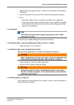
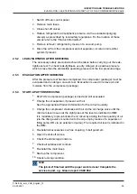
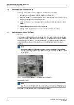
After the compressor has run for the initial 100 operating hours:

i.

Drain the oil and refill the compressor with the correct amount of fresh oil.

ii.

Replace the running oil discharge filter element with the “permanent“ filter
element in accordance with the filter replacement instructions.

iii.

Inspect suction gas filter (refer to the Compressor Service Instruction
Manual).

iv.

Exchange or clean oil suction filter element.

v.

Check the compressor shaft seal for leakage. If excessive (more than 1 cc/hr)
contact your compressor supplier

vi.

Retighten the coupling mounting bolts with the torque settings as given by the
coupling manufacturer.

vii.

Verify and if necessary, correct the torque settings of all foundation bolts as
given in Compressor Service Instruction Manual.

3.3

First maintenance

Hint!

For complete conditional service schedules and service intervals,
refer to Guideline for Conditional maintenance.
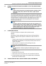
After the refrigerating plant has been modified, inspect/clean the
suction gas filter(s) and the oil filters.
After the refrigerating plant has been modified, the oil must be
changed.

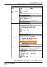
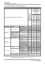
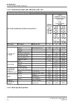
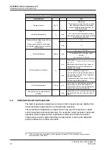
Maintenance

Number of operating hours


100

> 100

Renewal of oil discharge filter

X

refer to Guideline for Conditional

Maintenance

Inspection of suction gas filter(s)

X

Inspection of oil suction filter

(strainer)

X

Oil analysis 

8

X

Inspection leakage shaft seal

X

8

Consult your oil supplier.

MAINTENANCE

Spare parts manual

P-NL-094_imm_VHS_English_13


26.07.2021

41

Summary of Contents for Grasso V 1100HS

Page 1: ...Reciprocating compressors for industrial refrigeration GEA Grasso VHS Installation and Maintenance instructions Original text P NL 094_imm_VHS_English_13 ...

Page 2: ...erwise without prior written consent of GEA This restriction also applies to the corresponding drawings and diagrams LEGAL NOTICE This publication has been written in good faith However GEA cannot be held responsible neither for any errors occurring in this publication nor for their consequences P NL 094_imm_VHS_English_13 2 26 07 2021 ...

Page 3: ...nt This manual must be careful read and understood prior to installing and servicing the compressor package Safety This manual is written with great care but the contractor installer is held responsible to examine this information and to take care of possible additional and or deviated safety measures Safety instructions It is the task of the contractor installer to inform and explain to his clien...

Page 4: ...t will corrode the inside and working components of the compressor To store the compressor fill it with dry nitrogen after fully evacuating it Warning The compressor oil filters oil lines etcetera are not filled with oil Pre lubrication is obligatory Refer Section 4 7 Page 58 Hint After the successful initial run of the compressor package the warranty chart must be filled in and returned to Grasso...

Page 5: ...ned in this manual For instance not all compressor series are suitable for all mentioned refrigerants or not all compressor series includes two stage compressors Directives Equipment is based on Pressure Equipment Directive PED 2014 68 EU regulations and according to Machine Directive MD 2006 42 EG regulations The applied standards are NEN EN IEC 60204 NEN EN ISO 12100 NEN EN ISO 13857 NEN EN 378 ...

Page 6: ...P NL 094_imm_VHS_English_13 6 26 07 2021 ...

Page 7: ... numbering Fig 1 Example cylinder numbering 6 cylinder compressor Booster or single stage operation 1 Booster operation applies if condensing temperature 5 oC 2 Single stage operation applies if condensing temperature 5 oC P NL 094_imm_VHS_English_13 26 07 2021 7 ...

Page 8: ...P NL 094_imm_VHS_English_13 8 26 07 2021 ...

Page 9: ...n 30 minutes consult Grasso Adjust the steps between up and down loading in such a way that the system is running stable Oil level 25 75 crankcase sight glass Control oil pressure suction pressure 8 bar g Lubricating oil pressure difference between 1 3 and 4 5 bar Setting approx 2 0 bar g After a mimimum of 15 minutes running time at an oil temperature of approx 50 oC Max discharge temperature 170...

Page 10: ...P NL 094_imm_VHS_English_13 10 26 07 2021 ...

Page 11: ...or shaft 28 1 4 7 Installing the drive guards if present 28 1 4 8 Initial oil warm up 28 1 4 9 Initial start up 28 Limitations of part load operation and start up 28 WIRING LOGIC NORMALLY OPEN UNLOADED START SOLENOID 29 Frequency controlled compressor 29 Pre start check list 29 1 4 10 Starting and stopping procedures 30 First start 30 Restart 31 Restart after a short standstill period of time less...

Page 12: ...ies part 3 of 3 48 Most operated cylinders 48 3 4 4 Package components 49 4 APPENDIX Product Information PI 50 4 1 GRASSO MAINTENANCE MONITOR 50 4 2 TECHNICAL DATA 51 4 3 GENERAL LIMITS OF OPERATION GRASSO VHS 51 4 4 PRECISE FIELD OF APPLICATION 52 4 5 DIAGRAMSGRAMS CAPACITY CONTROL 54 4 6 LUBRICATING OILS choice and recommendations 56 4 6 1 STRONGLY RECOMMENDED OIL TYPES 56 4 6 2 ACCEPTED NH3 OIL...

Page 13: ...nsible for arranging the dual safety valve according the Pressure Equipment Directive 2014 68 EU 1 3 INSTALLATION Warning The compressor is not charged with oil therefore DO NOT start the compressor before it has been installed and prepared according to Grasso s instructions This section contains instructions for the proper installation of a Grasso compressor package Before the compressor package ...

Page 14: ... 3 1 Moving instructions and storage For loose component or compressor package weights refer either to the relevant component type plate or package lay out or to the suppliers document For bare compressor weights see Product Information Caution Every precaution must be taken while moving the package to its final location Pushing pulling or climbing on any package component or piping can easily cre...

Page 15: ...ngs so as to prevent damage to piping and components Warning DO NOT use the compressor or motor or oil separator hoisting eyes to move the package These hoisting eyes are intended for lifting loose components only and not for the entire package Bare compressor or loose components Determine the dead weight of the particular component see Product Information ED prior to moving a bare compressor or l...

Page 16: ...g and maintenance access the compressor package should be installed with sufficient free space around it Hint Refer to Product Information for minimum requirements 1 3 5 Foundation requirements Hint Compressor package has to be mounted on a concreted block On request Grasso can calculate the exact dimensions of the concrete block based on the compressor size and operating conditions This paragraph...

Page 17: ...Page 18 Section 1 3 5 4 Page 21 1 3 5 1 Concrete structure Fig 4 Concrete block 1 Cork board 2 Concrete base 3 Concrete Floor 4 Sand The concrete block for compressor and motor or compressor package should have a profile as illustrated in Page 17 and made according to the following recommendations The concrete block should be set on firm footings or on a floor capable of carrying the weight of the...

Page 18: ... 3 5 2 Anchoring After the concrete block has cured the anchors should be installed as shown above and in case of a package in accordance with the package lay out drawing Templates should be made to locate the anchor bolts or chemical anchors to match the holes in the bottom flange of the base frame Grout the mortar according to the supplier instructions Install chemical anchors as illustrated in ...

Page 19: ... base frame base frame cannot be removed easily 3 Drilling angle 1 3 5 3 Mounting the base frame on a concrete block General After the space between base frame and concrete base has been filled up with a filling grout the package base frame must be secured tightly to the foundation block or floor INSTALLATION AND PREPARATION FOR USE INSTALLATION P NL 094_imm_VHS_English_13 26 07 2021 19 ...

Page 20: ...velled on each frame side Adjust the frame on each adjusting place until all frame sides are horizontal This space largely depends on the sort of grout or mortar used Determine this space according to the instructions of the grout or mortar supplier Finishing with a self levelling grout After levelling has been completed the adjusting bolt ends must be greased to avoid bonding to the self levellin...

Page 21: ...ng at least 10 mm above the concrete base Fig 8 Grouting details of bare compressor on concrete block Legend 1 Self leveling grout 2 Foundation anchor 3 Layer of self leveling grout 10 15 mm 4 Temporary barrier strip aroud each compressor foot 5 Complete cured concrete block CF Compressor foot WL Width of grout layer WL WC 40 mm WC Width of compressor foot WL WC 40 mm 1 3 6 Connecting to refrigera...

Page 22: ...ng by clips or brackets in two directions Install stop valves piping and accessories such that there is no load exerted on the compressor Recommendation Fig 9 To ensure quick and easy maintenance work the following is recommended 1 In all situations install a removable section of pipe 200 mm on the suction flange of the compressor 2 In case oil separator is not mounted onto the package install a r...

Page 23: ... manual not supplied by Grasso 1 3 8 Earthing connections Grasso compressors and packages are equipped with litz wires and earth connecting points To avoid leakage current flowing through the components disconnect all litz wires when arc welding After all installation functions are completed reconnect the litz wires and ground the package to earth 1 3 9 Separately delivered components Hint Check w...

Page 24: ... 18 hours 1 4 2 EVACUATION DRYING THE REFRIGERATING SYSTEM For evacuation of compressor only refer to Section 2 5 Page 34 Procedure to evacuate and to dry a system i STATUS System is filled with nitrogen and no oil has been added oil prevents any trapped moisture from boiling off ii Verify that all valves in that part of the system to be evacuated are opened refer also to the plant manual iii Conn...

Page 25: ...ator if present iv Charge the compressor crankcase with oil via the oil charge valve Warning Pre lubrication just before the first start is obligatory Hint Filling of the afore mentioned components is also possible by means of a separate oil filling pump via the oil charge valves mounted onto the oil pump housing 1 4 3 1 Oil quantities VHS Number of cylinders Shaft seal housing incl internal circu...

Page 26: ...device is installed 1 4 5 2 PRESSURE SETTINGS Pressure safety limit switches Suction pressure 1 Setting 5oC below design evaporating temp Min 0 3 bar a Suction and intermediate pressure Setting Max refer to Product Information PI Setting 5oC above design condensing temp Discharge pressure Max 24 bar a Grasso V 700HS Grasso V 1100HS Grasso V 1400HS Grasso V 1800HS Lubrication oil pressure differenc...

Page 27: ...lubricaton Fig 12 Oil lubrication pressure regulator A Fig 13 Oil control pressure regulator B Pre lubrication valve P Caution Oil charge valve P for lubrication circuit this connection to be used for pre lubrication of the oil circuit 2 The oil pressure regulator is adjusted at the works but it may occur that this setting should be corrected during the initial run and also if the value 1 5 or 2 5...

Page 28: ...plugs Hint If the valve lifting fails check the control oil pressure regulator 1 4 6 Checking direction of rotation of motor shaft Prior to installing the intermediate coupling element the direction of rotation of the motor shaft must be checked The direction of rotation can be determined from the arrow sticker at the oil pump 1 4 7 Installing the drive guards if present Only after the compressor ...

Page 29: ...the minimum allowed compressor speed has been achieved and the specified lubrication oil pressure has been established 5 Energise the NO solenoid 5 seconds before stopping until the compressor is stopped completely 1 4 9 3 Frequency controlled compressor Hint In case of frequency controlled compressors a separate instruction 00 87 041 is required If you don t have this instruction consult Grasso 1...

Page 30: ...re refer to the Product Information Check crankcase oil level refer to Section 2 4 1 Page 34 If by pass valve between suction and discharge line of the compressor is present The by pass valve between suction and discharge line of the compressor has to be opened at the same time as the start release signal is given 2 Start the compressor and check whether the oil pressure increases Warning The time...

Page 31: ...t standstill period of time less than 1 month Refer to Section 1 4 10 2 Page 31 1 4 10 4 Restart after a long standstill period of time After a seasonal standstill 1 to 6 months or maintenance operations Warning After a standstill period of time more than 1 month pre lubrication just before starting is always obligatory Refer Section 4 7 Page 58 Check settings of control and safety equipment Proce...

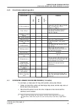
Page 32: ...tallation operating conditions and local regulations In the case of automatically controlled plants the periodical inspection are particularly important The table below sums up all the points on the compressor that have to be inspected or maintained along with inspection and maintenance frequencies 2 2 Survey of periodical inspections Apart from the check points in the table below the sound produc...

Page 33: ...ressor standstill the lower part of the crankcase must remain warmer than the surroundings 20 C NH3 Adjustment and operation of pressure safety switches Refer also to instructions of switch manufacturer Capacity control if provided Switching frequency of the compressor Number of operating hours Check the number of operating hours in view of any maintenance operations to be carried out 2 3 STEPS FO...

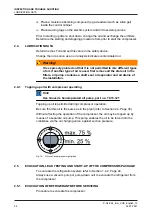
Page 34: ...he installation 2 4 1 Topping up oil with compressor operating Hint Use Grasso s hand operated oil pump part no 18 13 121 Topping up oil is permitted during compressor operation Be sure that this oil is the same as in the plant refer to Section 2 4 Page 34 Without affecting the operation of the compressor the oil may be topped up by means of a separate oil pump This pump enables the oil to be forc...

Page 35: ...sor package 2 5 4 START UP AFTER SERVICING 1 STATUS Compressor package is dried and still evacuated 2 Charge the oil separator if present with oil See the appropriate Product Information for the correct quantity 3 Charge the compressor crankcase with oil via the oil charge valve until the minimum level is seen at the sight glass at the level as indicated in IMM It is mandatory to pre lubricate the...

Page 36: ...oil suction filter and compressor suction gas filter s depends on the condition of the refrigeration system Besides the maintenance schedules it is recommended to exchange all filters when the compressor is overhauled and also in case the refrigeration plant has been modified Hint An oil discharge oil running in filter is factory mounted This oil filter must be exchanged after max 100 running hour...

Page 37: ...can be inspected and repaired or replaced if necessary later 2 9 COMPRESSOR PURGING Procedure to purge the compressor after maintenance jobs STATUS Stop valves of suction discharge and oil return line are still closed refer to Section 2 5 Page 34 and compressor is filled with oil refer to Section 2 6 Page 36 i Connect a vacuum pump to the evacuation purging valve s and evacuate as prescribed by lo...

Page 38: ...e compressor It is emphatically pointed out that the cause of a failure must often be sought in the refrigeration installation itself Therefore it is necessary besides this table also to consult the plant manual INSPECTION AND TROUBLE SHOOTING TROUBLESHOOTING TABLE GRASSO RECIPROCATING COMPRESSORS P NL 094_imm_VHS_English_13 38 26 07 2021 ...

Page 39: ...ir or renew D Suction pressure too low 1 Suction stop valve not fully open Open fully 2 Suction gas strainer blocked Renew 3 Injection control not adjusted correctly Re adjust control 4 Too little refrigerant in installation Top up with refrigerant 5 Suction pressure gauge defective Renew E Crankcase frosted or wet 6 Warning Stop compressor and contact installation engineer 1 Liquid refrigerant in...

Page 40: ...ted properly or defective Re adjust or renew 2 Defective oil pressure and or suction pressure gauge if present Repair or replace J Too low lubricating oil pressure 1 Too little oil in crankcase Top up oil 2 Disturbed oil circuit Oil suction and or discharge filter is dirty Renew the element of oil suction filter and or oil discharge filter 3 Lubricating oil pressure regulator not adjusted properly...

Page 41: ...compressor supplier vi Retighten the coupling mounting bolts with the torque settings as given by the coupling manufacturer vii Verify and if necessary correct the torque settings of all foundation bolts as given in Compressor Service Instruction Manual 3 3 First maintenance Hint For complete conditional service schedules and service intervals refer to Guideline for Conditional maintenance After t...

Page 42: ...l becomes 10 000 running hours fixed Maintenance to execute to be monitored and registered by the operator 3 4 1 Description Maintenance A B and C General The following maintenance has to be distinguished 1 Small maintenance Maintenance A Yearly inspection or every 5000 running hours at 1500 rpm or every 6000 hours at 1200 rpm whatever comes first 2 Medium maintenance Maintenance B 3 Large mainten...

Page 43: ...Inspection of pistons and cylinder liners Most activated cylinders Description maintenance C 1 Maintenance B activities 2 Major inspection General Complete disassembly required as far as necessary to inspect or replace parts as prescribed by the maintenance table Replacement of bearings inspection replacement of all main components like crankshaft cylinder liners pistons and valves as prescribed a...

Page 44: ...L Product Information PI Installation and Maintenance Manual IMM Service Instruction Manual SIM 2 Unless otherwise stated All checkpoints have to be visually assessed for irregularities like leakages fractures overheating discolourations dents bursts presence of sludge debris and solid particles etc 3 If applicable also the original manufacturer s documentation has to be consulted Particularly for...

Page 45: ... before re starting Used or filtered oil should NEVER be added to a compressor under any circumstance Use only new oil as selected from the Grasso oil table Oil charging via the suction line of the compressor is not allowed Oil and oil return systems The quality of the oil effects the oil consumption and the life time of the moving parts For oil return systems or systems in which soluble oil is be...

Page 46: ...LEAN CLEAN Oil cooler fan and heat exchanger CLEAN CLEAN CLEAN Lubrication control system Lubrication oil pressure regulator CHECK CHECK CHECK Control oil system Control oil pressure regulator CHECK CHECK CHECK CAPACITY CONTROL SYSTEM Control oil lines connections INSPECT INSPECT Hydraulic Capacity control actuators CHECK CHECK Push handle valve lifting CHECK CHECK O rings shaft guides Seals CHECK...

Page 47: ...Camring INSPECT Note For A maintenance keep inspection limited to 1 or 2 most frequently activated cylinders or cylinder s nearest to the compressor s shaft end Refer Section 3 4 3 4 Page 48 PISTON CONNECTING ROD ASSEMBLY Piston assembly Piston body INSPECT INSPECT Piston rings INSPECT REPLACE Gudgeon pin INSPECT MEASURE Connecting rod assembly Small end bearing bushing INSPECT MEASURE Tightening ...

Page 48: ...ture Fixation Intake suction filter screen CLEAN CLEAN Crankcase oil heating CHECK CHECK CHECK Oil return orifices HP LP INSPECT INSPECT INSPECT Safety relief valve s CHECK Inside CLEAN CLEAN CLEAN BASE FRAME Structure INSPECT INSPECT Fixation INSPECT INSPECT Vibration dampers INSPECT INSPECT COMPRESSOR PROTECTION SAFETY CONTROL DEVICES Temperature gauges sensors switches transmitters Connection l...

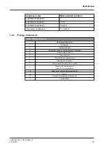
Page 49: ...oupling alignment 3 Oil level float switch on compressor and oil separator 4 Pressure safety switches 5 Pressure gauges 6 Thermostats and thermometers 7 Electrical control system 8 Oil return protection and oil return system 9 Electric motor and thermistors Consult motor manufacturer 10 Base frame vibration dampers and bolts 11 Piping 12 Oil cooler oil side and air side and fan 13 Thermo Master MA...

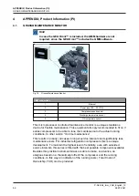
Page 50: ...aintenance to the actual running conditions In other words On time maintenance This results in nearly all cases in longer service intervals and significantly less maintenance costs For industrial refrigeration compressors this is a unique development To maintain the highest level of reliability even with extended service intervals this series is fitted with the best possible components available B...

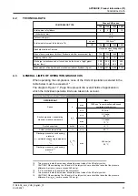
Page 51: ... are taken into account General limits and fields of operation REFRIGERANT NH3 Speed n max 1500 min 1 in combination with speed controlled electric motor min 500 min 1 Suction pressure evaporating pressure crankcase pressure po to min 0 3 bar a 55 C max 7 0 bar a 13 C Suction superheat delta t min 0 C Actual suction temperature ta min 50 C Discharge pressure condensing pressure tc saturated conden...

Page 52: ...he oil type used A minimum actual oil viscosity of 10 cSt in the bearings is always required Oil return temperature Toil_ret min 40 C and Tc 5K Indicated value is the lowest return oil oil in the oil separator and or other oil return source temperature at which the return of oil is allowed Capacity control running time fully unloaded max When GEA Omni controller and oil cooler are applied 10 minut...

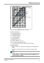
Page 53: ...hift downwards for Δto 0 K and or part load operation Procedure and data Diagram is based on continuous full load operation suction superheat 0K for NH3 For continuous minimum part load i e more than 30 minutes consult Grasso Hint Always consult the suppliers and the sales selection software tools of the manufacturer to determine the precise field of application for an actual compressor selection ...

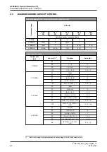
Page 54: ...700HS 25 1 50 1 2 1 75 1 2 3 1 2 100 1 2 3 4 1 2 3 V 1100HS 33 3 4 50 3 4 2 1 67 3 4 5 6 2 83 3 4 5 6 1 2 3 100 3 4 2 5 6 1 1 2 3 V 1400HS 25 5 6 37 5 6 8 2 50 5 6 8 7 1 2 62 5 6 8 1 3 2 4 75 5 6 2 4 1 3 3 4 87 5 6 7 2 4 1 3 1 3 4 100 5 6 7 8 2 4 1 3 1 2 3 4 V 1800HS 30 5 7 8 40 5 7 8 6 4 50 5 7 8 9 10 1 60 5 7 8 9 10 6 1 4 70 5 7 8 9 10 1 2 1 2 80 5 7 8 6 3 4 1 2 2 3 4 16 Refer to the swept volum...

Page 55: ... Solenoids 90 5 7 8 3 4 9 10 1 2 1 2 3 100 5 7 8 9 10 1 2 3 4 6 1 2 3 4 16 Refer to the swept volume expressed as a percentage of the full load swept volume APPENDIX Product Information PI DIAGRAMSGRAMS CAPACITY CONTROL P NL 094_imm_VHS_English_13 26 07 2021 55 ...

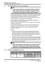
Page 56: ...rankcase is expected Remarks 1 Using ISO VG100 oils to increase viscosity at high expected cranckcase temperatures makes no sense as the friction heat will increase that much that the oil temperature limit related to the minimum viscosity of 10 cSt will also be exceeded Only in case of expected high refrigerant concentrations in the cranckcase this viscosity gradeoil is an alternative 2 Using ISO ...

Page 57: ...ol LPT 68 54 68 CASTROL Icematic 299 56 CPI CP 1009 68 69 H2 EXXON MOBIL Zerice S46 Zerice S68 Arctic 300 48 68 68 47 68 FUCHS Reniso KS 46 Reniso KC 68 KROON OIL Carsinus FC 46 68 46 PETRO CANADA Reflo 68A Reflo XL 58 H2 H2 Klüber Summit RHT 68 68 H2 Kuwait Petroleum Q8 Stravinsky C 55 SHELL Refrigeration Oil S2 FR A 68 SUN OIL Suniso 3 5 GS Suniso 4 GS Suniso 5 G Suniso 4 SA 43 55 94 57 TEXACO C...

Page 58: ...y running is minimized or even better eliminated Dry running of oil pump bearings pistons and piston rings will initiate and after initiation worsen the wear of the parts mentioned and eventually even damage the crank shaft and cylinder liners or even more parts When pre lubrication 1 Before initial start up 2 Before start up after overhauling compressor 3 Before start up after renewal of oil 4 Be...

Page 59: ...APPENDIX Product Information PI P NL 094_imm_VHS_English_13 26 07 2021 59 ...

Page 60: ...ne of the largest providers of innovative equipment and process technology GEA Group is listed in the STOXX Europe 600 Index We live our values Excellence Passion Integrity Responsibility GEA versity GEA Refrigeration GEA Refrigeration Netherlands N V Parallelweg 25 5223 AL s Hertogenbosch Netherlands Phone 31 0 73 6203 911 info gea com gea com ...

Reviews: