background image


PRODUCT INFORMATION 


LIQUID CHILLER GRASSO DX R 

200 ... 1600 


_601011_pi_dxr_gbr_1_.doc 

 33  

WEIGHTS AND CHARGES - TYPES RR 450 ... RR 800 


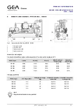
fig. 9: 

Ammonia liquid chiller - Types RR 450 ... RR 800 

Cold water outlet 

Cold water inlet 

Cooling water outlet 

Cooling water inlet 

Dimensions and weights


For standard conditions water outlet evaporator 6°C, water outlet condenser 32°C


Chiller Type: 

L (mm) 

W (mm) 

H (mm) 

Weight without 

charging (kg) 

Operating 

weight (kg) 

RR 

450 3800 1550 1800 3661 

4094 

RR 

500 3800 1550 1800 4086 

4569 

RR 

600 4200 1550 2100 4985 

5521 

RR 

800 4200 1550 2100 5500 

6154 

Charging quantities


Chiller Type: 

Oil charge (dm

3

Refrigerant charge 

(kg) 

Standard connection 

cold water 

Standard connection 

cooling water 

RR 450 

110 

30 

NB 100 

NB 125 

RR 500 

110 

33 

NB 125 

NB 125 

RR 600 

110 

40 

NB 125 

NB 125 

RR 800 

110 

53 

NB 150 

NB 150 


Hint! 

Project-related deviations are possible! 

Summary of Contents for Grasso DX 600

Page 1: ..._601011_pi_dxr_gbr_1_ doc 1 Liquid Chiller Grasso DX R 200 1600 Product Information ...

Page 2: ...ublished by means of printing photocopying microfilm or otherwise without prior written consent of Grasso This restriction also applies to the corresponding drawings and diagrams LEGAL NOTICE This publication has been written in good faith However Grasso cannot be held responsible neither for any errors occurring in this publication nor for their consequences ...

Page 3: ...r_gbr_1_ doc 3 SYMBOLS USED IN THIS MANUAL Danger This is an important warning Non observance these warnings can cause accidents with relevant damages on persons or serious damages on the compressor or refrigerating plant Warning Attention Caution Important Hint Tip Note ...

Page 4: ......

Page 5: ...dard ammonia liquid chiller DX series type RR 200 RR 350 16 5 2 P I diagram for standard ammonia liquid chiller DX series type LR 200 LR 350 VR 200 VR 350 18 5 3 P I diagram for standard ammonia liquid chiller DX series type RR 450 RR 800 20 5 4 P I diagram for standard ammonia liquid chiller DX series type LR 450 LR 800 VR 450 VR 800 22 5 5 P I diagram for standard ammonia liquid chiller DX serie...

Page 6: ......

Page 7: ...id chiller DX series type RR 450 RR 800 20 fig 5 P I diagram for standard ammonia liquid chiller DX series type LR 450 LR 800 VR 450 VR 800 22 fig 6 P I diagram for standard ammonia liquid chiller DX series type RR 750 RR 1600 24 fig 7 P I diagram for standard ammonia liquid chiller DX series type LR 750 LR 1600 VR 750 VR 1600 26 fig 8 Ammonia liquid chiller Types RR 200 RR 350 32 fig 9 Ammonia li...

Page 8: ...onnect on site The DX chillers are designed according to the 3 different concepts of Grasso screw compressors Because of that compact designed DX chiller carried out The standard model types valid for the named conditions see overview cold water 12 C 6 C and cooling water 26 C 32 C Each model size can be delivered with exact adapted evaporators and condensers deviating of standard as well as with ...

Page 9: ...eat exchanger R shell and tube heat exchanger The DX chiller series consists of 12 model types with established Grasso screw compressors The capacity range covers from 200 kW up to 1600 kW regarding air conditioning application for manufacturing cold water The only used refrigerant is ammonia The working principle is the dry evaporation with shell and tube heat exchangers as evaporator and condens...

Page 10: ...0 N 748 200 RR 800 P 798 200 RR 1000 R 966 250 RR 1200 S 1198 315 RR 1600 V 1547 355 Series LR overview Chiller Type Compressor Chiller capacity kW 2 Motor nom capacity kW LR 200 C 187 75 LR 250 D 221 75 LR 300 E 265 90 LR 350 G 314 110 LR 450 H 402 132 LR 500 L 474 160 LR 600 M 601 200 LR 750 N 731 250 LR 800 P 787 250 LR 1000 R 945 315 LR 1200 S 1171 355 LR 1600 V 1506 450 1 water outlet evapora...

Page 11: ...W VR 200 C 191 55 VR 250 D 227 75 VR 300 E 272 75 VR 350 G 322 90 VR 450 H 411 110 VR 500 L 485 132 VR 600 M 615 160 VR 750 N 748 200 VR 800 P 798 200 VR 1000 R 966 250 VR 1200 S 1198 315 VR 1600 V 1547 355 Hint For information on the dimensions weights charging quantities and connections see separate data sheets 3 water outlet evaporator 6 C condensing temperature 32 C ...

Page 12: ...dry evaporation R Condenser type R shell and tube heat exchanger L air cooled condenser V evaporative condenser R Evaporator type R shell and tube heat exchanger 800 Nominal chiller capacity kW related to cold water operation S Design of liquid chiller without marking Standard design S Special design related to heat exchangers and optional equipment NH3 Refrigerant ...

Page 13: ...at delivered by secondary refrigerant During the operation of the screw compressor oil is injected into the working chamber and then separated again from the refrigerant in the discharge side oil separator The oil in compressor heated is either cooled via a oil cooler to inlet temperature or liquid refrigerant is injected into the screw compressor for reaching a discharge temperature which is agre...

Page 14: ...ng of all operating and fault messages as well as process variables The display is operated via a robust keypad having function and system keys 4 6 Low voltage Power Panel The low voltage power panel is completely wired with all chiller sensors and actuators as well as prepared for connection with the external incoming feeder cable 4 7 safety devices against pressure exceedings The chiller is equi...

Page 15: ...e ratio Vi depending on its design A hydraulic Vi adjusting system guarantees compression at the lowest loss possible under the respective operating conditions and thus saves drive power see the Screw Compressor Datasheet The internal volume ratio is variable depending on the design and type of the compressor across a range from Vi 2 6 to Vi 5 5 4 9 5 L2 Bus communication of compressor control dev...

Page 16: ...agram for standard ammonia liquid chiller DX series type RR 200 RR 350 A Water W Cooling water 010 Compressor 012 Control slide position indicator 015 Compressor drive motor 016 Motor current limiter 017 Motor winding protection 020 Oil separator 030 Water cooled oil cooler 040 Oil pump 050 Solenoid valve block for capacity control 065 Stop valve oil circuit 075 Oil pressure regulating valve ...

Page 17: ...85 Stop valve bypassing integrated check valve 350 Safety pressure limiter 360 Oil heater 365 Stop valve oil separators oil drain 395 Pressure transducer oil pressure after filter 420 Stop valve compressor housing draining 450 Service port 455 Service port 470 Stop valve oil pump suction side 475 Stop valve oil pump discharge side 500 Condenser 505 Service port 510 Expansion valve 520 Evaporator 5...

Page 18: ...ope of supply Grasso 010 Compressor 012 Control slide position indicator 015 Compressor drive motor 016 Motor current limiter 017 Motor winding protection 020 Oil separator 040 Oil pump 050 Solenoid valve block for capacity control 065 Stop valve oil circuit 075 Oil pressure regulating valve 085 Stop valve venting 090 Stop valve oil draining oil charging 095 Coupling 100 Pressure transducer suctio...

Page 19: ...arators oil drain 395 Pressure transducer oil pressure after filter 420 Stop valve compressor housing draining 450 Service port 455 Service port 470 Stop valve oil pump suction side 475 Stop valve oil pump discharge side 500 Condenser 505 Service port 510 Expansion valve 515 Safety valve 520 Evaporator 530 Resistance thermometer water flow 535 Flow controller 540 refrigerant draw in valve 545 Serv...

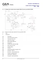
Page 20: ... 010 Compressor 012 Control slide position indicator 015 Compressor drive motor 016 Motor current limiter 017 Motor winding protection 020 Oil separator 025 Oil filter with multi function block 030 Water cooled oil cooler 036 Oil filter element 040 Oil pump 050 Solenoid valve block for capacity control 065 Stop valve oil circuit 070 Stop valve oil pump discharge side 075 Oil pressure regulating va...

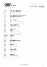
Page 21: ...gas line 255 Stop valve bypassing valve 250 285 Stop valve bypassing integrated check valve 340 Overflow valve 350 Safety pressure limiter 360 Oil heater 365 Stop valve oil separators oil drain 395 Pressure transducer oil pressure after filter 405 Stop valve suction pressure transducer 460 Service port 500 Condenser 505 Service port 510 Expansion valve 520 Evaporator 525 Service port 530 Resistanc...

Page 22: ...mpressor 012 Control slide position indicator 015 Compressor drive motor 016 Motor current limiter 017 Motor winding protection 020 Oil separator 025 Multi function block 036 Oil filter element 040 Oil pump 050 Solenoid valve block for capacity control 065 Stop valve oil circuit 070 Stop valve oil pump discharge side 075 Oil pressure regulating valve 080 Control valve injection oil 085 Stop valve ...

Page 23: ...ot gas line 255 Stop valve bypassing valve 250 285 Stop valve bypassing integrated check valve 340 Overflow valve 350 Safety pressure limiter 360 Oil heater 365 Stop valve oil separators oil drain 395 Pressure transducer oil pressure after filter 405 Stop valve suction pressure transducer 460 Service port 505 Service port 510 Expansion valve 515 Safety valve 520 Evaporator 530 Resistance thermomet...

Page 24: ...600 A Water B Cooling water 010 Compressor 012 Control slide position indicator 015 Compressor drive motor 016 Motor current limiter 017 Motor winding protection 020 Oil separator 025 Oil filter with multi function block 030 Water cooled oil cooler 036 Oil filter element 040 Oil pump 045 Suction filter 050 Solenoid valve block for capacity control 065 Stop valve oil circuit 070 Stop valve oil pump...

Page 25: ...rcuit 250 Check valve hot gas line 255 Stop valve bypassing valve 250 340 Overflow valve 350 Safety pressure limiter 360 Oil heater 365 Stop valve oil separators oil drain 395 Pressure transducer oil pressure after filter 405 Stop valve suction pressure transducer 460 Service port 465 Service port 500 Condenser 505 Service port 510 Expansion valve 520 Evaporator 530 Resistance thermometer water fl...

Page 26: ... B Scope of supply Grasso 010 Compressor 012 Control slide position indicator 015 Compressor drive motor 016 Motor current limiter 017 Motor winding protection 020 Oil separator 025 Multi function block 036 Oil filter element 040 Oil pump 045 Suction filter 050 Solenoid valve block for capacity control 065 Stop valve oil circuit 070 Stop valve oil pump discharge side 075 Oil pressure regulating va...

Page 27: ...assing oil cooler 250 Check valve hot gas line 255 Stop valve bypassing valve 250 340 Overflow valve 350 Safety pressure limiter 360 Oil heater 365 Stop valve oil separators oil drain 395 Pressure transducer oil pressure after filter 405 Stop valve suction pressure transducer 460 465 505 Service port 510 Expansion valve 515 Safety valve 520 Evaporator 530 Resistance thermometer water flow 535 Flow...

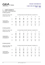
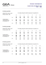
Page 28: ...ller type RR 250 Secondary refrigerant outlet temperature at evaporator C Refrigerating capacity in kW Driving capacity in kW 10 6 2 0 2 6 10 32 264 55 227 54 193 53 178 52 164 52 139 50 116 49 38 253 64 217 62 185 60 171 59 157 58 132 57 111 56 Cooling medium outlet temperature at condenser C 45 246 69 211 67 180 65 166 64 152 64 128 63 107 61 DX chiller type RR 300 Secondary refrigerant outlet t...

Page 29: ...let temperature at evaporator C Refrigerating capacity in kW Driving capacity in kW 10 6 2 0 2 6 10 32 478 93 411 91 351 90 324 88 298 87 251 84 211 83 38 460 108 395 104 337 101 310 100 285 99 240 96 201 95 Cooling medium outlet temperature at condenser C 45 447 116 383 113 327 110 301 109 277 108 233 106 194 103 DX chiller type RR 500 Secondary refrigerant outlet temperature at evaporator C Refr...

Page 30: ...t outlet temperature at evaporator C Refrigerating capacity in kW Driving capacity in kW 10 6 2 0 2 6 10 32 923 180 798 177 681 173 630 170 581 167 493 163 415 159 38 890 208 768 201 659 195 608 192 561 190 475 185 400 182 Cooling medium outlet temperature at condenser C 45 875 225 754 218 643 212 594 209 548 207 463 203 389 196 DX chiller type RR 750 Secondary refrigerant outlet temperature at ev...

Page 31: ...emperature at evaporator C Refrigerating capacity in kW Driving capacity in kW 10 6 2 0 2 6 10 32 1406 268 1198 262 1048 256 970 251 896 247 762 238 643 232 38 1368 311 1183 298 1018 288 942 283 870 279 738 271 622 265 Cooling medium outlet temperature at condenser C 45 1342 334 1160 322 997 313 922 308 852 304 722 297 608 285 DX chiller type RR 1600 Secondary refrigerant outlet temperature at eva...

Page 32: ...orator 6 C water outlet condenser 32 C Chiller Type L mm W mm H mm Weight without charging kg Operating weight kg RR 200 3500 1480 1820 2538 2781 RR 250 3500 1480 1820 2719 2981 RR 300 3500 1480 1820 3043 3359 RR 350 3500 1480 1820 3272 3617 Charging quantities Chiller Type Oil charge dm3 Refrigerant charge kg Standard connection cold water Standard connection cooling water RR 200 90 13 NB 100 NB ...

Page 33: ...or 6 C water outlet condenser 32 C Chiller Type L mm W mm H mm Weight without charging kg Operating weight kg RR 450 3800 1550 1800 3661 4094 RR 500 3800 1550 1800 4086 4569 RR 600 4200 1550 2100 4985 5521 RR 800 4200 1550 2100 5500 6154 Charging quantities Chiller Type Oil charge dm3 Refrigerant charge kg Standard connection cold water Standard connection cooling water RR 450 110 30 NB 100 NB 125...

Page 34: ... Chiller Type L mm W mm H mm Weight without charging kg Operating weight kg RR 750 4000 1650 2000 5889 6569 RR 1000 4500 1860 2250 6998 7887 RR 1200 4500 1860 2250 7769 8833 RR 1400 4500 1860 2350 8780 10150 RR 1600 4500 1860 2350 9789 11464 Charging quantities Chiller Type Oil charge dm3 Refrigerant charge kg Standard connection cold water Standard connection cooling water RR 750 150 50 NB 150 NB...

Page 35: ...it chiller safety by monitoring of pressure and temperatures 2 Running a fail safe startup and shutdown routine 3 Screw compressor capacity control either manually or automatically 4 Automatic refrigerant injection into the evaporator for chillers DX Series only Technical data Model type Standard housing with an engineered modular Grasso configuration and a standard terminal Power supply 115 230 V...

Page 36: ...ting temperature or temperature of secondary refrigerant Controlled by a three position controller Set point and neutral zone can be parameter Set point adjustment Setpoints can be adjusted through the unit controller by a higher level master control using analog signal 4 20 mA Start up modes MANUAL SC unit chiller is switched ON OFF manually independently of the refrigerating demand AUTO SC unit ...

Page 37: ...onnected to a higher level master control using this method The master control must know the MPI or PROFIBUS DP Master Slave protocol 2 via floating contacts To higher level control Status messages SCP Chiller ready SCP Chiller fault The control slide position may be passed on as an analogue signal using a buffer amplifier From higher level control Status messages SCP Chiller ON OFF Fault acknowle...

Page 38: ...unt of water in the plastic vessel is sufficient to absorb the total refrigerant charge with the decrease in solubility by warming up being taken into account After leaving the gas distribution pipe the air bubbles through the water and the ammonia is absorbed The cleaned air is recirculated to the machine room If the ammonia concentration falls below the threshold value the ventilator is switched...

Page 39: ...400 approx 1100 approx 2200 ABSA 100 I approx 1400 approx 1100 approx 2200 ABSA 150 II approx 2200 approx 1300 approx 2200 ABSA 200 II approx 2200 approx 1300 approx 2200 ABSA 250 III approx 2200 approx 1600 approx 2200 ABSA 300 IV approx 2700 approx 1600 approx 2400 ABSA 350 IV approx 2700 approx 1600 approx 2400 ABSA 25 V approx 1200 approx 700 approx 1600 ...

Page 40: ...ing The absorber is positioned as shown in the Figure fig 12 Absorption device ABSA view 1 Vessel made of ammonia resistant plastic 2 High pressure ventilator 3 Connecting sleeve 4 Demister with separating package 5 Diffuser laid out for connection to venting systems 6 Gas distribution pipe 7 Liquid level indicator ...

Page 41: ... connecting sleeves I Suction connection of high pressure ventilator Ø 76 Ø 103 Ø 140 Ø1604 II Diffuser air outlet Ø 160 III Safety pipe connection NB 40 IV Charging connection DN 32 5 V Discharging connection NB 32 2 VI Sampling connection NB 10 2 4 according to type of ventilator 5 ball cock design ...

Page 42: ...2000 1500 1200 2100 700 ABSA 300 IV up to 300 IV 2500 1500 1200 2500 670 ABSA 350 IV up to 350 IV 2500 1500 1200 2920 780 ABSA 25 V up to 25 I 1000 600 750 210 350 Type Required air flow m3 h Fan type Motor output 7 Gas distribution pipe diameter x l mm Weight without filling kg ABSA 50 I 680 HRD 14 5 2 2 110 x 500 200 ABSA 100 I 1080 HRD 60 4 4 0 110 x 750 230 ABSA 150 II 1410 HRD 65 4 4 0 137 x ...

Page 43: ..._pi_dxr_gbr_1_ doc 43 Type Required air flow m3 h Fan type Motor output 7 Gas distribution pipe diameter x l mm Weight without filling kg ABSA 300 IV 2240 HRD 65 7 7 5 137 x 750 510 ABSA 350 IV 2485 HRD 65 7 7 5 137 x 1000 510 ABSA 25 V 430 HRD 1 5 1 1 70 x 500 130 ...

Page 44: ......

Reviews: