GEA FK40/560 N Assembly Instructions Manual Download Page 20

20

09716-01.2013-DGbFEIT

rCn

  D 
 GB
  F
  E
  I
 TR
 CN

7

|

 Accessories

7.1  Capacity regulation

For a description, see technical information "Capacity regulation" (Item No. 09900)
If the capacity regulator is factory-fitted, it is integrated into an extra, dedicated cylinder cover. For 
retrofits, it is supplied with the cylinder cover. The regulator closes one cylinder bank (capacity regula

-

tion approx. 50%).

A  screw-in  option  is  provided  for  the  sensor  element  on  the  hot  gas  side  of  the  compressor


housing (see Chap. 9). Connect the thermal protection thermostat in series with the control line.

Technical Data:

Switching voltage max. : 

24 V DC 

Switching current max.  : 

2.5 A at 24 V DC

Switch-off temperature : 

145 °C ± 5 K

Switch-on temperature : 

approx. 115 °C

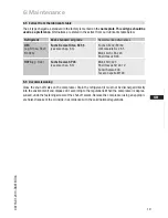
7.2  Thermal protection thermostat (Item No. 07595)

FK40 / ...

... N + TK

... K

Designation

Art.-Nr.

Art.-Nr.

Special accessory 12 V

08703

08708

Special accessory 24 V

08704

08709

ATTENTION!     Capacity-regulated operation alters the gas speeds and pressure 

 ratios of the refrigerating plant: Adjust the suction line routing and 
 dimensioning accordingly, do not set the control intervals too close and  
do not let the system switch more than 12 times per hour (refriger-
ating plant must have reached a state of equilibrium). Continuous 
operation  in  the  control  stage  is  not  recommended  as  the  gas 
velocity in the plant system under certain circumstances does not 
guarantee sufficient oil return to the compressor with activated  
capacity regulator for a compressor speed below 1200 - 1500 rpm.


  We recommend switching to unregulated operation (100% capacity)  


  for at least 5 minutes per capacity-regulated operating hour. An  


  assured oil return can also be realised by a 100% capacity require- 


  ment after each compressor restart as otherwise the compressor  


  can  also  be  shut  down  in  the  regulated  operating  time  by  the  


  thermostat.


   Electrical actuation of the solenoid valve: Normally open, (corre-

sponds to 100 % compressor capacity).


   Cylinder  covers  for  capacity  regulation  are  marked  with  the 

 designation "CR" (Capacity Regulator).

Summary of Contents for FK40/560 N

Page 1: ...60 K FK40 655 K FK40 390 TK FK40 470 TK FK40 560 TK FK40 655 TK FKX40 390 N FKX40 470 N FKX40 560 N FKX40 655 N FKX40 390 K FKX40 470 K FKX40 560 K FKX40 655 K FKX40 390 TK FKX40 470 TK FKX40 560 TK F...

Page 2: ...use of the compressor can lead to serious or fatal injury Observe the safety instructions contained in these instructions These instructions must be passed onto the end customer along with the unit in...

Page 3: ...e inclination 4 3 V belt drive 4 4 Main bearing load 4 5 Electromagnetic coupling assembly 4 6 Pipe connections 4 7 Pipes 4 8 Operating the shut off valves 4 9 Operating mode of the lockable service c...

Page 4: ...hines and as such call for heightened caution and care in handling The maximum permissible overpressure must not be exceeded even for testing purposes WARNING Risk of burns Depending on the operating...

Page 5: ...Any other use of the compressor is prohibited The Bock refrigerating compressor named in the title is intended for installation in a machine within the EU according to the EU Directives 2006 42 EC Mac...

Page 6: ...safety and efficiency are concerned Compact four cylinder compressor in V design Four capacity ranges Lightweight aluminum design Lubricating oil pump with oil pressure relief valve independent of rot...

Page 7: ...ure side 4 Machine number 5 Factory filled oil type Fig 3 2 2 Name plate example 2 3 Type key example K specially for air conditioning N specially for air conditioning or normal cooling TK specially f...

Page 8: ...we recommend the use of a thermal protection thermostat Accessories Chap 7 When capacity regulators are used the limits of application can move When operating in the vacuum range there is a danger of...

Page 9: ...uction gas superheat K Suction gas superheat K Suction gas temperature C Suction gas temperature C Fig 4 Fig 5 20 30 50 70 80 20 10 10 0 20 30 t C o t C c 82 30 40 60 90 t 25 C oh toh 20 K R134a 20 30...

Page 10: ...bereich reduzierte Sauggastemperatur FK R22 tc t0 toh Dtoh Verdampfungstemperatur C Verfl ssigungstemperatur C Sauggas berhitzung K Sauggastemperatur C Uneingeschr nkter Anwendungsbereich reduzierte S...

Page 11: ...essor for transport damage before starting any work Fig 8 Fig 9 Transport and suspension unit on the eyebolt Fig 8 or direct on the discharge line valve Fig 9 Fittings e g pipe holders additional unit...

Page 12: ...the magnetic field of the electromagnetic clutch the front bearing flange has a snug fit 148 h8 see Fig 12 To connect the magnetic field loosen the 4 cheese head screws M8 on the bearing flange see F...

Page 13: ...inhibit oxidation products scale The pipe connections have stepped internal diameters so that pipes with standard millimetre and inch dimensions can be used The connection diameters of the shut off va...

Page 14: ...on 2 2 Fig 17 Opening the shut off valve a Spindle 1 turn to the left counter clockwise as far as it will go Shut off valve fully opened service connection 2 closed Fig 18 Opening the service connecti...

Page 15: ...compressor for transport damage 5 2 Pressure strength test DANGER Bursting The compressor must only be pressurised using nitrogen N2 Never pressurise with oxygen or other gases The maximum permissibl...

Page 16: ...es The oil level must be visible in at least one sightglass ATTENTION Avoid overfilling the system with refrigerant To avoid shifts in concentration zeotropic refrigerant blends e g R407C must always...

Page 17: ...especially important to ensuring fault free operation The complete refrigerant circuit must be correctly executed and clean inside Heavy shocks and vibrations to the shaft as well as continuous cycli...

Page 18: ...alve is maintenance free However constant leakage can occur after blowing off due to abnormal operating conditions This leads to reduced performance and increases the compressed gas temperature In thi...

Page 19: ...th the valid national regulations 6 Maintenance 6 5 Extract from the lubricants table The oil type charged as standard in the factory is marked on the name plate This oil type should be used as a pref...

Page 20: ...ty regulated operation alters the gas speeds and pressure ratios of the refrigerating plant Adjust the suction line routing and dimensioningaccordingly donotsetthecontrolintervalstoocloseand do not le...

Page 21: ...t of the driving unit kgm 2 Lubri cation Oil pump FK40 390 4 385 33 5 34 0 22 7 8 28 1 1 8 2 0 0 0043 Forced lubrication Rotation independent FK40 470 466 40 5 33 0 28 1 1 8 35 1 3 8 FK40 560 554 48 3...

Page 22: ...onnections Dimensions in K Design Shaft end Centre of gravity Dimensions in mm Dimensions in mm Fig 20 Fig 21 169 ca 110 ca 170 M SV A SV1 A1 C E G 13 232 210 145 329 ca 370 4x ca 320 325 F DV B B1 L...

Page 23: ...kable 7 16 UNF B Connection discharge side not lockable 1 8 NPTF B1 Connection discharge side lockable 7 16 UNF C Connection oil pressure safety switch OIL 1 8 NPTF D Connection oil pressure safety sw...

Page 24: ...12100 2 EN 12693 EN 349 A partly completed machine may only be put into operation when it has been established that the machine into which the partly completed machine is to be installed conforms to t...

Page 25: ...eichnet WARNUNG Dieses Symbol weist darauf hi dass ungenaues Befolgen oder Nichtbefolg von Anweisungen zu Sch den an Personen am Verdichter oder an der K lteanlage f h kann GEFAHR Dieses Symbol weist...

Page 26: ...re than 50 countries Founded in 1881 the company is one of the largest providers of innovative equipment and process technology GEA Group is listed in the STOXX Europe 600 Index GEA Refrigeration Tech...

Reviews: