


12
09716-01.2013-DGbFEIT
rCn
D
GB
F
E
I
TR
CN
4
|
Compressor assembly
During operation with capacity controllers (Accessories, Chap. 7), the changing load can cause
increased running noises and belt drive vibrations.
4.3 V-belt drive
4.4 Main bearing load
4.5 Electromagnetic clutch assembly
ATTENTION! Inappropriately designed belt drives, especially belt knocking
or excessive tensioning forces can cause compressor damage!
Make sure that the drive belt is designed correctly, e.g. by using
tensioners and selecting the belt profile and the belt length.
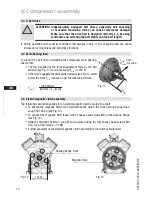
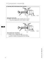
The following description applies for an electromagnetic clutch secured to a shaft.
To absorb the magnetic field of the electromagnetic clutch, the front bearing flange has a
snug fit Ø 148 h8 (see Fig. 12).
To connect the magnetic field, loosen the 4 cheese head screws M8 on the bearing flange
(see Fig. 12).
Slide the magnetic field to a snug fit and re-attach using the four cheese head screws M8
(Fig. 13). Screw torque = 34 Nm.
Further assembly of the electromagnetic clutch according to the clutch manufacturer.
Fig. 12
Bearing flange, front
Magnetic field
Fig. 13
148 h8
To prevent the belt drive overloading the compressor main bearing,
ensure that:
The force applied at the force engagement force by the belt
tension (see Fig. 11) must not exceed F
max
= 2750 N.
If the force engagement point shifts forwards (see Fig.11, small
point), the force F
max
reduces as per the following formula:
F
max
= 245 kNmm
(90 mm + L
1
[mm])
F
max=
2750 N
M
bmax=
245kNmm
L
1
(mm)
Fig. 11


