D
GB
F
E
19
96460-08.2018-DGb
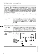
In the factory, the motor is switched for direct starting (YY). For part winding start (Y/YY), remove the
bridges and connect the motor feed cable according to the circuit diagram:
400 V
Direct start YY
Part winding start Y/YY
L1
L2
L3
L1
L2
L3
L1
L3
L2
PTC
PW II
PW I
PTC
ATTENTION Property damage possible.
Failure to comply results in reversed fields of rotation and can cause
motor damage. After the motor has started up with part winding 1,
part winding 2 must be switched on after max. 1 second delay. Fail-
ure to comply can be detrimental to the service life of the motor.
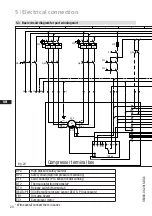
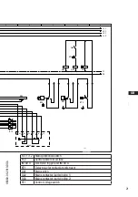
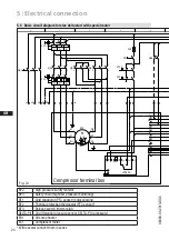
Ensure that power is supplied via QA2 to winding 1 (50 %)
(1U1 / 1V1 / 1W1) and via QA3 to winding 2 (50 %) (2U1 / 2V1 / 2W1).
The motor contactors (QA2 / QA3) are each to be rated for approx.
50 % of the max. operating current.
5
|
Electrical connection


