


D
GB
F
E
I
Ru
21
09652-06.2015-DGbFEIRu
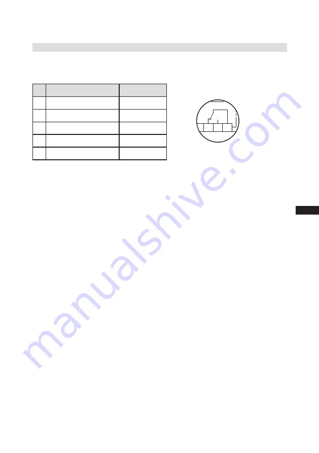
Relay position INT69 G
B2 12 14 11
Fig. 24
5.10 Function test of the trigger unit INT69 G
Before commissioning, after troubleshooting or making changes to the control power circuit, check
the functionality of the trigger unit. Perform this check using a continuity tester or gauge.
Gauge state
Relay position
1.
Deactivated state
11-12
2.
INT69 G switch-on
11-14
3.
Remove PTC connector
11-12
4.
Insert PTC connector
11-12
5.
Reset after mains on
11-14
5| Electrical connection


