GE Appliances
General Electric Company
Louisville, Kentucky 40225
31-9127
2800 Series
3800 Series
GE Consumer & Industrial
Technical Service Guide
JUNE 2005
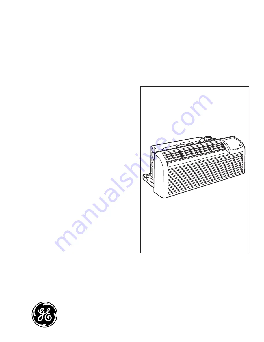
Zoneline
Generation III
Airconditioners
All manuals and user guides at all-guides.com
all-guides.com


