D
IRECTION
5771498-100, R
EVISION
6
V
ENUE
™ S
ERVICE
M
ANUAL
Chapter 3 - System Setup
3-23
P R E L I M I N A R Y
The current drain will vary depending on the mains voltage.
•
At 240 VAC the current may be up to 2.08 A.
•
At 100 VAC the current may be up to 5 A.
3-5-4
Connections on the I/O Rear Panel
NOTE:
Accessory equipment connected to the analog and digital interfaces must be certified according to the
respective IEC standards (e.g. IEC60950 for data processing equipment and IEC60601-1 for medical
equipment). Furthermore, all complete configurations shall comply with the valid version of the system
standard IEC60601-1-1. Everybody who connects additional equipment to the signal input part or signal
output part of Venue™ , configures a medical system, and is therefore responsible that the Ultrasound
system complies with the requirements of the valid version of IEC60601-1-1. If in doubt, consult the
technical service department or your local representative for GE.
3-5-4-1
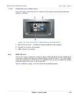
Connect Ethernet
Connect the network cable to the Ethernet connector on the External I/O.
The connector is located on the rear side of Venue™ .
3-5-4-2
Connect USB Flash Card
Insert the USB Flash Card in one of the USB ports on the Venue™ .
Table 3-14 Electrical Specifications for all Venue™ Models
Voltage
100-240 VAC
±10%
Power Consumption
500 VA
Frequency
50-60 Hz
Summary of Contents for Venue R1
Page 477: ......


