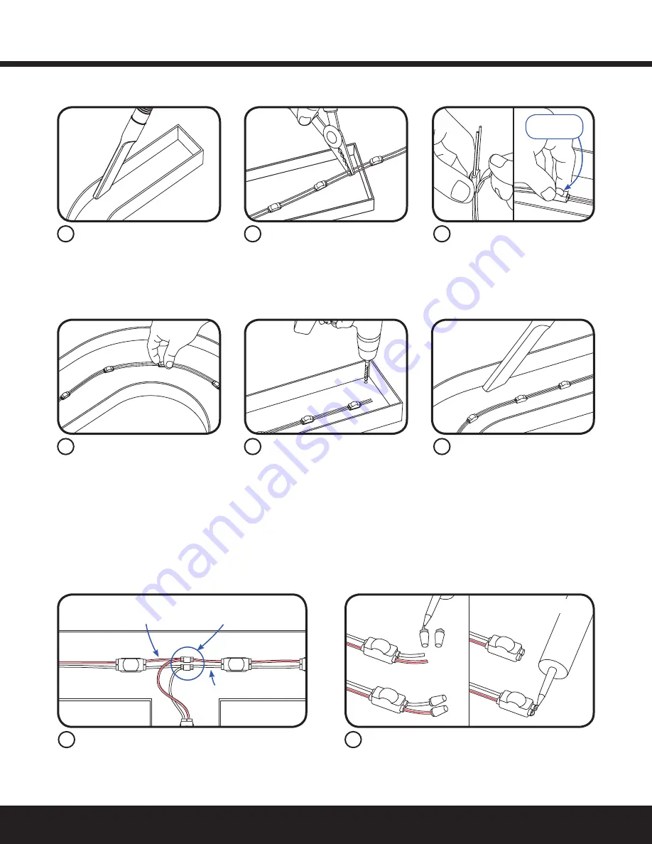
Measure and cut Tetra LED strip
to the appropriate length for
each letter. Cuts can be made
between any of the modules.
Use the double stick tape or
electrical grade RTV silicone to fix
LED module within the channel
letter.
Drill a 1/4-inch (6.4 mm) hole
near the LED strip and grommet
the hole for supply wire access.
Remove all the debris from the
inside of the channel letter and
replace the sign face.
NOTE: For halo-lit applications LED modules should be mounted on UL
recognized clear acrylic or polycarbonate. The light output from the LED
system should be directed back into the sign enclosure. This will allow for
uniform backlighting of the sign and will provide simple mounting.
Before you begin, clean surfaces
and remove all debris from the
inside of the channel letter.Clean
the surfaces with a 50:50 mixture
of isopropyl alcohol (IPA) and
water and let dry.
Layout Modules
Remove tape backing and stick LED
modules into place. When using tape
apply approximately 15 psi pressure
on the module (avoid the lens dome
surface) for 5 seconds, full bonding
strength after 24 hours. Continue until
you have reached the end of the strip.
Do not
press lens
Electrical Connections
NOTE: Do not use connectors pre-filled with silicone grease/mineral base protective grease or use silicone grease to seal connections.
Cap wires
Optional: Cut wires flush
Must cap all exposed wires with appropriate wire
connectors and seal with electrical grade RTV silicone.
Optional: Cut wires flush to the module and seal with
electrical grade RTV silicone.
Connect LED strips using in-line (IDC) connectors or
twist-on wire connectors.
NOTE: Seal all connections in wet locations with
electrical grade RTV silicone.
Red stripe (+)
White (-)
Seal all connections in wet locations
with electrical grade RTV silicone
2
5
1
4
3
6
1
2
Tetra
®
Atom
Installation Guide
3


