3
Mounting inside Concord Commercial enclosure
Note:
This module is UL listed as a subassembly and must be
mounted in the same enclosure as the Concord 4 in UL
systems.
1.
Unplug the panel AC power transformer and disconnect the
backup battery.
2.
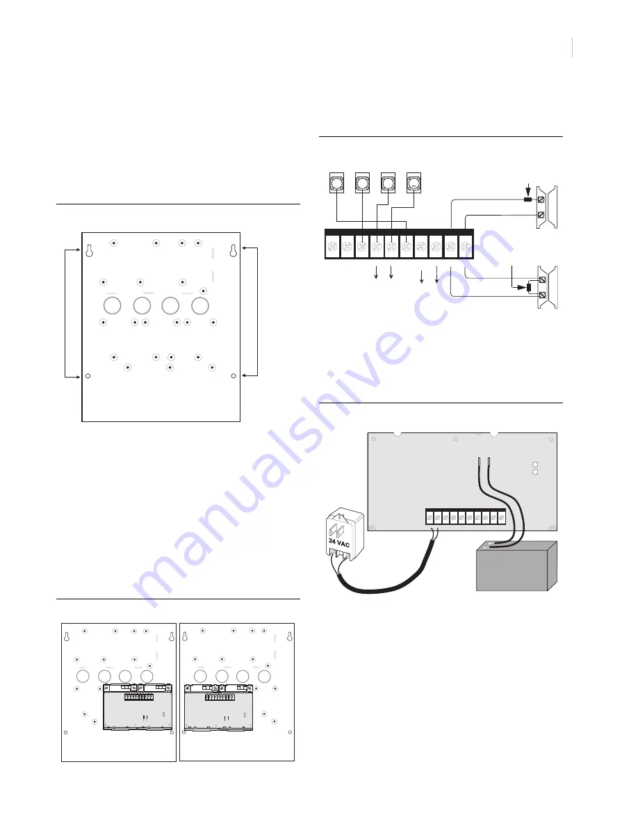
Remove the necessary knockouts for wire access (Figure 7).
3.
Place the cabinet at the desired location and mark the
cabinet mounting holes and knockouts (Figure 7).
Figure 7.
Commercial enclosure power supply mounting holes and knockouts
4.
Drill holes and insert the appropriate anchors where studs
are not present.
5.
Run wires from all devices to be powered, to the power
supply.
6.
Run a 4-conductor, 22-gauge or larger stranded wire from
the power supply to the panel.
7.
Run a 2-conductor, 18-gauge stranded wire from the power
supply to the AC transformer location.
8.
Feed all wires through the knockouts and secure the cabinet
to the wall with the included screws.
9.
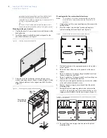
Secure the power supply to the cabinet using either the right
side or left side power supply mounting holes, with the six
self-tapping screws included with the power supply (Figure
8).
Figure 8.
Power supply mounted in commercial enclosure
Wiring
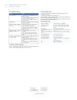
Connect the power supply to the panel terminals and devices as
shown in Figure 9.
Figure 9.
Power supply wiring connections to panel and devices
Power Up
Use the following procedure for powering up the power supply
and panel to verify bus communication.
1.
Verify that all wiring at the panel and devices are correct.
2.
Connect the power supply backup battery to the battery
terminals on the power supply board (Figure 10).
Figure 10. Power supply AC and DC power connections
3.
Wire the power supply AC transformer to the power supply
board, then plug in the transformer (Figure 10).
The green LED should turn on to indicate power is present.
The red LED should be off for the moment.
Note:
If the green LED is not on, unplug the power supply AC
power transformer, disconnect the backup battery, and
proceed to Table 2 in “Troubleshooting”.
4.
Connect the panel backup battery and plug in the panel AC
power transformer.
The panel should automatically scan for new bus devices
and the red LED on the power supply board should flicker
to indicate bus communication with the panel.
5.
If using the optional zone input, learn the zone into panel
memory (see panel
installation instructions
).
Cabinet
Mounting
Holes (4)
Knockouts (4)
Power Supply
Mounting
Holes
Right Side Mounting
Left Side Mounting
2 4 V A C 2 4 V A C + 1 2 V
B U S A
B U S B
G N D
+ 1 2 V
O U T
Z O N E
G N D
G N D
3
4
5
6
+ 1 2 V
A
B
G N D
B U S
To power
N/O circuit with2k Ohm
inputs on
devices
Resistor (49-45
4)
N/C circuit with 2k Ohm
Resistor (49-454)
To bus
devices
2 4 V A C 2 4 V A C + 1 2 V
B U S A
B U S B
G N D
+ 1 2 V
O U T
Z O N E
G N D
G N D
+
_
+
_
RED
BLACK


