

2
1TQC1930E0005 IS REV.A DEC.2020 (475A484AAP0
0
1 - REV 003)
—
We reserve the right to make technical
changes or modify the contents of this
document without prior notice. With regard
to purchase orders, the agreed particulars
shall prevail. ABB Inc. does not accept any
responsibility whatsoever for potential
errors or possible lack of information in
this document.
We reserve all rights in this document and in
the subject matter and illustrations
contained therein. Any reproduction,
disclosure to third parties or utilization of
its contents – in whole or in parts – is
forbidden without prior written consent of
ABB Inc. Copyright© 2020 ABB
All rights reserved
—
ABB Inc.
305 Gregson Drive
Cary, NC 27511
electrification.us.abb.com
GE is a trademark of GE.
Manufactured by ABB Ltd under license
from General Electric Company.
After the inner cover is in place, the unit
should be energized and breaker operation
checked out by operating the circuit breakers.
Verify correct output voltage and polarity.
The outer cover should then be closed and
secured. Padlock mounting holes are
provided and may be used to secure the
outer cover of the unit.
Loading
Loads may be applied either from line-to-line
or from line-to-neutral. Care should be taken
to balance the loads, if possible.
Do not exceed the rated current on any
transformer phase where:
Current = Nameplate kVA or Current = kVA .
208 X sqrt 3
120 X 3
Preventive maintenance
The only preventive maintenance required is
periodic inspection of connections, operation
of circuit breakers, and removal of
accumulated interior dust, dirt and lint.
Renewal parts
Field repairs are usually uneconomical except
for replacement of the circuit breakers. No
spare parts or renewal parts are
recommended. If conditions of operation
dictate the need for standby equipment, a
complete spare unit is recommended.
Wiring diagrams
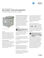
SERVICE CENTER MINI-UNIT SUBSTATION
INSTRUCTION AND INSTALLATION SHEET
(Three-Phase - 22.5 kVA Models)
FIGURE 1 - TYPICAL WIRING DIAGRAM
DO NOT MAKE OR CHANGE CONNECTIONS
WHILE UNIT IS ENERGIZED !!
Page 2 of 2
—
Figure 1 - typical wiring diagram
NOTE: Do not make or change connections
while unit is energized.
H1
1
2
(3)
(4)
5
6
7
8
(9)
(15)
(10)
(16)
11
17
13
12
18
14
7 6 5 4 3 2 1
7 6 5 4 3 2 1
7 6 5 4 3 2 1
H2
H3
X1
H1
NEUTRAL IS BONDED
TO ENCLOSURE BY
USE OF BONDING
SCREW
SECONDARY MAIN
3-POLE TYPE THQL
70A, 240V
PRIMARY MAIN
3-POLE TYPE TED
70A, 480V
GROUND
WHEN
REQUIRED
SECONDARY
MAIN
BREAKER
PRIMARY
MAIN
BREAKER
H2
LINE
1
LINE
3
LINE
2
H3
X2
X0
X1
X2
X3
X3
N
EU
TR
A
L
N
EU
TR
A
L
N, XO


