background image

   Press the 

<

 or 

>

 button to set differential value.

   Press the 

RIGHT

 button to advance to the next screen.


Note:

 Default factory setting is 2°F/1°C for each stage. 

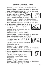
4.  

Temperature Differential—Stage 2 

(1–9°F/1–5°C) Heat Pump (HSH) only 

Set the number of degrees between when 

stage 1 turns on and stage 2 turns on.

   Press the 

<

 or 

>

 button to set differential value.

   Press the 

RIGHT

 button to advance to the next screen.


Note:

 Default factory setting is 2°F/1°C for each stage.

5.  

Minimum Cool Setpoint (60, 64, 66, 68, 

70, 72, 74, 76°F) (15, 17, 19, 20, 21, 22, 

23, 24°C)

   Adjust to control the minimum Cool set 

temperature allowed.

   Press the 

<

 or 

>

 button to select.

   Press the 

RIGHT

 button to advance to the next screen.


Note:

 Default factory setting is 60°F/15°C.

6.  

Maximum Heat Setpoint (65, 70, 72, 74, 

76, 78, 80, 85°F) (18, 21, 22, 23, 24, 26, 

27, 29°C)

   Adjust to control the maximum Heat set 

temperature allowed.

   Press the 

<

 or 

>

 button to select.

   Press the 

RIGHT

 button to advance to the next screen.

 Note:

 Default factory setting is 85°F/29°C.

7.  

Room temperature offset (+9°F to –9°F) 

(+5°C to –5°C)

   Adjust to calibrate displayed room 

temperature to match actual room 

temperature.

 Press 

the 

<

 or 

>

 button to select.

   Press the 

RIGHT

 button to advance to the next screen.

 Note:

 Default factory setting is 0°F/0°C.

11

CONFIGURATION MODE

Summary of Contents for RAK148H2

Page 1: ... 3 INSTALLATION 4 WIRING DIAGRAMS 8 CONFIGURATION MODE 10 OPERATING FUNCTIONS 12 TESTING THERMOSTAT 13 TROUBLESHOOTING 15 WARRANTY 16 THERMOSTAT Digital OWNER S MANUAL INSTALLATION INSTRUCTIONS RAK148H2 LIAF271 49 7757 1 01 20 GEA ...

Page 2: ...mostat only as described in this manual Electrical rating 24 VAC 18 30 VAC 1 amp maximum per terminal 4 amp maximum total load Operating temperature range 40 F 99 F 4 C 37 C Temperature set range 60 F 85 F 15 C 29 C Accuracy 1 F 0 5 C System configurations Factory Setting 2 stage heat heat pump resistance heat 1 stage cool 2 speed fan Alternate Setting 1 stage heat resistance heat 1 stage cool 2 s...

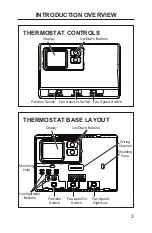
Page 3: ...Display Up Down Buttons Function Switch Fan Auto On Switch B GH GL Y W C R COOL COOL OFF OFF HEAT HEAT RESET RESET RIGHT RIGHT LEFT LEFT AUTO AUTO ON ON HIGH HIGH LOW LOW Display Up Down Buttons Wiring Channel Mounting Hole Function Switch Fan Auto On Switch Mounting Hole Configuration Buttons Fan Speed Switch Fan Speed High Low ...

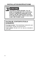
Page 4: ...s and wall anchors Tools needed ULOO ZLWK Ǝ ELW KDPPHU VFUHZGULYHU and putty WARNING ELECTRICAL SHOCK HAZARD Turn off power by unplugging the unit or by removing the fuse or switching the appropriate circuit breaker to the OFF position before removing the existing thermostat Failure to do so could result in risk of electric shock ...

Page 5: ...2 Remove cover of old thermostat This should expose the wires 3 Label the existing wires with the enclosed wire labels before removing wires 4 After labeling wires remove wires from wire terminals 5 Remove existing thermostat base from wall 6 Refer to the following section for instructions on how to install this thermostat INSTALLATION INSTRUCTIONS ...

Page 6: ...itch on the thermostat to Off 3 Remove the cover by inserting and twisting a coin or screwdriver in the slots on the top of the thermostat 4 Put thermostat base against the wall where you plan to mount it Make sure wires will feed through the wire opening in the base of the thermostat 5 With the base level mark the placement of the mounting holes 6 Set thermostat base and cover away from working a...

Page 7: ...sing on the corresponding terminal contact See the Wiring Diagrams section of this manual NOTICE Make sure exposed portion of wires do not touch other wires 13 Gently tug wire to be sure of proper connection Double check that each wire is connected to the proper terminal 14 Replace cover on thermostat by snapping it in place 15 Plug the unit in or turn on power to the system at the main service pa...

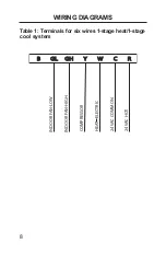
Page 8: ...8 WIRING DIAGRAMS Table 1 Terminals for six wires 1 stage heat 1 stage cool system B GH GH Y W C R R GL GL INDOOR FAN LOW INDOOR FAN HIGH COMPRESSOR 24 VAC COMMON 24 VAC HOT HEAT ELECTRIC ...

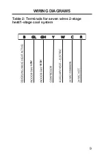
Page 9: ...9 Table 2 Terminals for seven wires 2 stage heat 1 stage cool system WIRING DIAGRAMS B GH GH Y W C R R GL GL LOW HIGH ...

Page 10: ...NOTE To exit configuration mode at any time slide the Function switch to Heat or Cool Configuration Mode Settings The setup screens for Configuration Mode are as follows 1 Temperature Scale F or C Choose Fahrenheit or Celsius Press the or button to select Press the RIGHT button to advance to the next screen NOTE Default factory setting is Fahrenheit 2 Heat System Check model number on the Hotpoint...

Page 11: ... 24 C Adjust to control the minimum Cool set temperature allowed Press the or button to select Press the RIGHT button to advance to the next screen Note Default factory setting is 60 F 15 C 6 Maximum Heat Setpoint 65 70 72 74 76 78 80 85 F 18 21 22 23 24 26 27 29 C Adjust to control the maximum Heat set temperature allowed Press the or button to select Press the RIGHT button to advance to the next...

Page 12: ...vices manual fan can operate Off is also used to access Configuration mode Cool In this mode the thermostat controls the cooling system Press the or button to set the desired temperature Heat In this mode the thermostat controls the heating system Press the or button to set the desired temperature ...

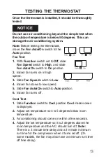
Page 13: ...peed 3 Slide Fan Speed switch to Low 4 Indoor fan slows to low speed 5 Slide Fan Auto On switch to Auto position 6 Indoor fan turns off Cool Test 1 Slide Function switch to Cool position Cool mode screen is displayed 2 Adjust set temperature so it is 5 degrees below room temperature 3 Air conditioning should come on within a few seconds 4 Adjust the set temperature so it is 2 degrees above the roo...

Page 14: ...s above room temperature 3 Heat should come on within a few seconds 4 Adjust the set temperature so it is 2 degrees below the room temperature and the heat should turn off Note There is a 3 minute time delay and a 3 minute minimum run time for the compressor when it turns on off On some models the fan may also have a minimum run time off time delay ...

Page 15: ...switch If set to ON position fan will run Room temperature is not correct Verify that wall hole is plugged with SXWW RU LQVXODWLRQ WR SUHYHQW DLUÀRZ from the wall cavity Adjust Tempera WXUH 2ႇVHW VHH RQ JXUDWLRQ 0RGH 5RRP WHPSHUDWXUH RႇVHW VHFWLRQ Compressor doesn t UXQ RU WXUQ Rႇ LP mediately when changing function or setting There is a 3 minute time delay and a 3 minute minimum run time for the ...

Page 16: ...roper power supply voltage accident fire floods or acts of God Ŷ Incidental or consequential damage caused by possible defects with this thermostat Staple your receipt here Proof of the original purchase date is needed to validate the warranty This warranty is extended to the original purchaser and any succeeding owner for products purchased for use within the USA and Canada In Alaska the warranty...

Reviews: