3
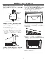
STEP 4: Installation of the wall sleeve in
the wall opening
3RVLWLRQWKHZDOOVOHHYHLQWRWKHZDOO5HIHUWRFKDUWRQSDJH
IRUURRPVLGHSURMHFWLRQ7KHUHDURXWVLGHHGJHRIWKH
ZDOOVOHHYHVKRXOGH[WHQGDWOHDVW´EH\RQGWKHRXWVLGH
ZDOOWREHDEOHWRFDXONSURSHUO\DQGSUHYHQWVHDOLQJWKH
GUDLQKROHVLQWKHUHDOÀDQJHRIWKHZDOOVOHHYHDQGWRIDFLO
-
itate easy installation of an accessory drain, if desired. (If it
LVGHVLUHGWRKDYHWKHUHDUJULOOHÀXVKRQWKHRXWVLGHDGULS
UDLOPXVWEHLQVWDOOOHGXQGHUWKHZDOOVOHHYHDQGFDXONLQJ
applied between the drip rail and wall sleeve.)
IMPORTANT:
Install wall sleeve level from side to side with a slight tilt
from front to rear. Use a level; no more than a 1/4” bubble
will be the correct wall sleeve slant to the outside.
For an internal drain, install level from front to rear.
Inside wall
Inside wall
)LUPO\VHFXUHWKHZDOOVOHHYHWRWKHZDOOVWUXFWXUHE\GULOOLQJ
KROHVLQWKHDSSURSULDWHORFDWLRQ'R127GULOODQ\KROHVLQ
the bottom of the wall sleeve.
8VHDSSURSULDWHVFUHZVODJ
bolts, etc. to attach the wall sleeve to the wall structure.
Secure case through
side and/or top only
2” min. from
case bottom
6HFXUHZDOOVOHHYHWKURXJK
side and / or top only
´PLQIURPZDOO
sleeve bottom
8VHDOLQWHOZKHQUHTXLUHGWRVXSSRUWEULFNDQGEORFNDERYH
the wall sleeve.
NOTE:
Do not drill any holes in the wall sleeve for electrical
connections.
Installation Instructions
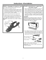
STEP 3: Preparation of the wall sleeve
,I¿HOGVXSSOLHGZDOOVOHHYHDQJOHVDUHWREHXVHGDQGPXVWEH
installed, proceed as follows:
3RVLWLRQWKHZDOOVOHHYHDQJOHVDURXQGWKHWRSDQGVLGHV
RIWKHDWWKHGHVLUHGORFDWLRQIURQWDQGUHDUZLWKDQJOHV
IDFLQJWRZDUGUHDURXWVLGH3RVLWLRQWKHDQJOHVYHUWLFDOO\
on each side of the to provide a level installation.
0DUNWKHWKURXJKWKHKROHVLQWKHDQJOHV
'ULOO´GLDPHWHUKROHVDWPDUNHGORFDWLRQVRQWKHZDOO
VOHHYHDQGDVVHPEOHWKHDQJOHVXVLQJRQO\[´VFUHZV
Install the screws from the outside of the wall sleeve.
NOTE: Do not drill any holes in bottom of the wall sleeve.
Roomside
Case angle
(field-supplied)
Block
Brick
Wall Sleeve

