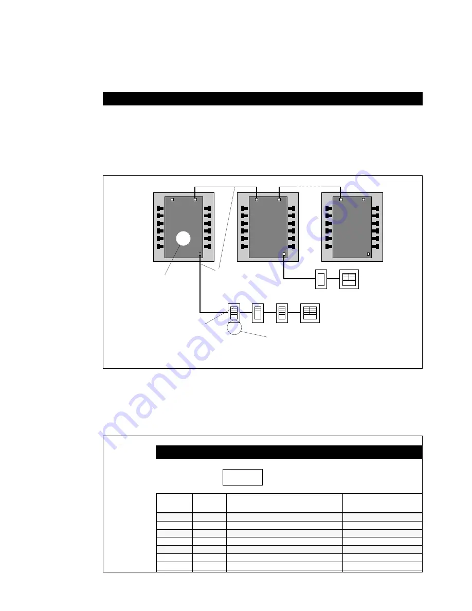
As shown in
Figure 1
below, dataline switches are numbered
sequentially beginning with 01-01 (Panel 01-Switch 01). A
single switch unit may have 1, 2, 4 or 8 buttons. Switch units
should be identified on the reflected ceiling plan showing the
number of buttons in each location. Check to confirm that the
correct switch unit has been installed at each location.
A separate
ProSys SWITCH DOCUMENTATION
form
should be used for each relay panel to record the number of
the switch and its number of buttons. Allow one line for each
button as shown on the form in
Figure 2
below. For example,
switch 01-01 has four buttons. The form should list all buttons
on each switch, even if you are not using all of them.
NUMBER AND DOCUMENT DATALINE SWITCHES
Any switch button may be softwired to control a single relay
or a group of relays within any single panel (see next page for
softwiring a dataline switch). For example, assume that you
want the top two buttons of a 4-button switch to control open
office areas associated with relays in Panel 01, while the
third button controls common areas (rest rooms and hallways)
in Panel 02. The form below shows how to record this intent
and also shows the labeling for each switch button. Finally,
write the switch number on the label in the lower right corner
of the switch base (see
Figure 4
on page 5).
Figure 1
DATALINE SWITCH DOCUMENTATION
SWITCH # BUTTON
RELAYS CONTROLLED
DESCRIPTION
(8
MAX
.)
-01
1
-01, -02
OFFICE - NW
"
2
-03, -04
OFFICE - NE
"
3
SPARE
"
4
"
-02
1
-15, -16
HALLWAYS NORTH
"
2
-17, -18
HALLWAYS SOUTH
Figure 2
PANEL #
01
01-01
01-02
02-01
02-02
01-03
01-04
02
xx
PANELS
NUMBERED
SEQUENTIALLY
BEGINNING
AT 01
DATALINE
18/4 AWG
1500 FT. MAX.
GE RLONWIRE-4P
DATALINE SWITCHES FOR EACH PANEL
NUMBERED SEQUENTIALLY (PANEL #-SWITCH #)
MAXIMUM TOTAL NUMBER OF RELAY PANELS AND DATALINE SWITCHES IS 64
SWITCH
BUTTONS
(#1 AT TOP)
RELAY
PANEL
RELAY
PANEL
RELAY
PANEL
01
Summary of Contents for ProSys DEH40206
Page 10: ......


