– 20 –
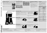
3. Remove the tub cover by lifting the 8 tabs.
4. Remove the agitator. Use agitator strap
(PN WX5X1326).
5. Remove the 7/16-in. hex head bolt and air bell
coupling from the transmission spline shaft.
Note:
•
The 1-11/16 in. hub nut is Stainless Steel and
has been torqued to 150 ft. lbs.
•
The word “LOOSEN” and an arrow appear on
the hub nut. Turn clockwise to remove.
Caution: Use only a rubber mallet, dead blow
hammer, or impact wrench to remove the hub nut.
Use of a steel head hammer may result in damage
to the spin basket.
6. Remove the left-handed, stainless steel hub nut
using a spanner wrench and a rubber mallet or
dead blow hammer, or an impact wrench.
Note: Hub nut must be tightened to 150 ft. lbs.
when reinstalling, see Spin Basket.
7. Remove the tub with motor and transmission
(see Tub With Motor and Transmission).
8. Place the tub with motor and transmission on its
side, and slide tub out of the unit.
Suspension
The tub and motor assembly (spin basket, tub,
motor, transmission, and leg and platform
assembly) is suspended by four rod and spring
assemblies. The rod and spring assemblies are
attached to each corner of the cabinet. They
extend down and connect to the leg and platform
assembly. This arrangement provides limited
movement to the tub and motor assembly,
independent of the cabinet when agitating and
spinning, thus reducing cabinet travel and vibration.
Front and rear suspension rod compressions vary
to compensate for the added weight of the motor.
The rods are color-coded to ensure that they are
replaced in the correct position (front - yellow, rear
- white).
The tub has 4 dampening straps attached to the
four corners of the cabinet. These straps prevent
excessive rotation and movement during agitation,
startup, and braking.
Rod
Spring Assembly
Bottom of
Basket
Remove
Nut
Lid Switch
3 Locking Tabs
Air Bell
Coupler
7/16" Bolt
Lid Switch
Summary of Contents for Profile WPRB9250
Page 6: ...4 Control Features WPRB9250 WPRB9220...
Page 35: ...33 Notes...


