background image

– 8 –

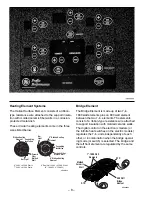
Bridge Element

The Bridge Element is made up of two 7-in.,
1800 watt elements plus an 800 watt element
between the two 7-in. elements. The elements
consist of a ribbon-type resistance wire attached
to support insulation with molded ceramic walls.
The digital control on the electronic models (or
the infinite heat switches on the electric models)
regulates the 7-in. units independently of each
other, or in combination when the bridge operat-
ing mode (or switch) is selected. The bridge and
the left front element are regulated by the same
controls.

GEA00902

RTD

RTD

800 Watt
Bridge
Element

Molded

Ceramic

Wall

7"-1800 Watt

Elements

Heating Element Systems

The Haliant Surface Element consists of a ribbon-
type resistance wire attached to the support insula-
tion with molded ceramic fiber walls in a corrosion-
protected metal dish.

These circular heating elements come in the three
sizes listed below.


4

4

Ceramic 
Fiber
Molded 

Element

Element

Ceramic Fiber

Element

Light

Hot Light

Ribbon Heating

Supporting
Insulation

Hot

Wall

6" 240 Volt-1200 Watts

7" 240 Volt-1500 Watts

(6"-1000W., 9"-1500W)

9" Dual Unit 240 Volt 2500 Watts

6" Ribbon Heating

Molded Wall

Supporting
Insulation

9" Ribbon Heating

GEA00798

Summary of Contents for Profile JP938

Page 1: ...UB 31 9070 01 01 MODEL SERIES TECHNICAL SERVICE GUIDE GE Consumer Home Services Training Electronic JP938 JP968 Electric JP340 JP350 JP930 JP960 Electronic Touch Control Electric Manual Control Cookto...

Page 2: ...ersonal injury disconnect power before servicing this product If electrical power is required for diagnosis or test purposes disconnect the power immediately after performing the necessary checks RECO...

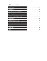
Page 3: ...troduction 2 Installation 3 Specifications and Nomenclature5 5 Warranty Information 6 Cooktop Features and Controls 7 Diagnostics 12 Mechanical Disassembly 18 Component and Connector Locator Views 27...

Page 4: ...element to fit the size of a metallic pan And the new warming feature keeps sauces and gravies warm or can be used as a normal heating element The controls lockout feature protects against power activ...

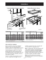
Page 5: ...ot interfere with cabinet structure at front 1 3 4 MIN clearance to side wall from cut out 1 1 2 MIN clearance to side wall from cut out 18 MIN to cabinet 1 3 4 to rear wall 13 MAX depth A Cooktop G E...

Page 6: ...appliance The branch circuit load for a counter mounted cooktop and not more than two wall mounted ovens all supplied from a single branch circuit and located in the same room shall be computed by ad...

Page 7: ...d under the control panel The letter designating the year repeats every 12 years Example T 1974 T 1986 T 1998 J P 9 6 8 B C Product J GE Cooking Product Configuration P Cooktop Feature Pack Designates...

Page 8: ...itation of incidental or consequential damages This war ranty gives you specific legal rights and you may also have other rights which vary from state to state To know what your legal rights are consu...

Page 9: ...68 36 in Electronic Cooktop JP938 30 in Electronic Cooktop JP930 30 in Electric Cooktop Before replacing the cooktop try using the cooktop cleaning procedure outlined in the Owner s Manual using the c...

Page 10: ...front element are regulated by the same controls GEA00902 RTD RTD 800 Watt Bridge Element Molded Ceramic Wall 7 1800 Watt Elements Heating Element Systems The Haliant Surface Element consists of a rib...

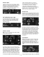
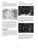
Page 11: ...arge and small surface elements OFF touch the ON OFF pad To turn ON the bridge element set the left front surface element to the desired setting Touch the BRIDGE pad The bridge element will energize t...

Page 12: ...2 beep signal will sound and the light will go out indicating the cooktop is unlocked Locking the cooktop will prevent surface elements from accidentally being energized by children or pets You may lo...

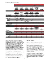
Page 13: ...JP960TC JP938WC JP930TC JP968CC JP960CC JP938CC JP930CC JP350CC JP968BC JP960BC JP938BC JP930BC JP350BC JP340BC Features 5 Ribbon 1500W 4400W 4400W 4400W 4400W 1200W 5 5 4 4 4 1 Appearance SS SS SS S...

Page 14: ...ystem 13 Triac Voltage Control 13 Pan Detection 14 Technician Mode 14 Fault Codes F codes 15 Line In Voltage Check 15 Temperature Check in Celsius 15 Frequency Check in Hertz 16 Calibration of the Ind...

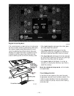
Page 15: ...Triac Voltage Control A triac fired control replaces the usual rheostat temperature control for each surface element The control receives feedback from the temperature sensor to allow for precise cont...

Page 16: ...after 1 minute Pan Size Feature When the pan detection feature is active the pan size feature is also active The pan size feature is designed to automatically recognize the size of a pan placed on the...

Page 17: ...9 recorded F codes The cooktop has multiple sensors one for each surface element Some F codes include a sensor number associated with a surface element The illustration below shows the sensor surface...

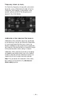
Page 18: ...rmanently store the pan detection thresholds in a new logic board that has never been cali brated Calibration is also performed to update the pan detection thresholds due to a physical change in the p...

Page 19: ...17 Fault Code Behavior Table...

Page 20: ...t 19 Switch Replacement 19 HOT SURFACE Light Replacement 20 Burner Replacement 20 Electronic Models 21 Glass and Cooktop Removal from Countertop 21 Touch Board and Cooktop Glass Replacement 22 Display...

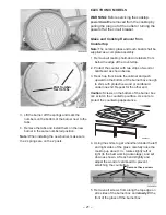
Page 21: ...ktop up about 4 in rotate slightly left or right to the best working advantage and set down as shown Lift each end slightly and adjust the wood or cardboard to prevent scratching the countertop 5 Remo...

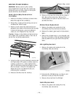
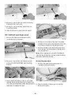
Page 22: ...ght Push in on the second light tab while still pushing the light down to release the light GEA00814 LR Burner Switch LR Burner Switch 4 Remove 4 screws from the switch mounting bracket 2 from each en...

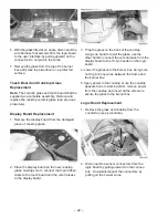
Page 23: ...iners from below the edge of the countertop 2 Protect the counter with two strips of wood or cardboard as shown below 3 Reach up from inside the cabinet and push upward on the bottom of the burner box...

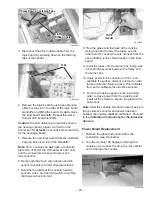
Page 24: ...shall be supplied as a complete assembly Remove and replace the cooktop ceramic glass see previous procedure Display Board Replacement 1 Remove the display board from the damaged piece of cooktop gla...

Page 25: ...EA00823 3 Disconnect the 26 pin ribbon cable from the logic board by pressing down on the latching tabs of the header Tabs Tabs GEA00824 4 Remove the logic board by using needle nose pliers to press i...

Page 26: ...ore reaching for the new power board 7 Remove the new power board from the anti static bag and reconnect the 26 pin wire har ness the main power connector and the burner box power connector to their o...

Page 27: ...e fails follow these steps Try calibrating the cooktop again beginning with step 1 from above Identify the sensor s that fails the calibration procedure If multiple sensors fail the calibration proced...

Page 28: ...mbers on the bottom of the heater next to the tabs 9 Using a nut driver remove the necessary screws from the outside of the burner box and lift the surface element support bracket to route the sensor...

Page 29: ...oard Display Board Touch Board Assembly Display Board Touch Board Assembly User Interface to Logic Board Wire Harness User Interface to Logic Board Wire Harness 26 Pin Ribbon Connector 26 Pin Ribbon C...

Page 30: ...er Box Pan Sensor Pan Sensor Power Connector Power Connector Temperature Sensor RTD Temperature Sensor RTD Heater Heater Ceramic Glass Top Ceramic Glass Top User Interface to Logic Board Wire Harness...

Page 31: ...port Bracket Support Bracket Burner Box Burner Box HOT SURFACE HOT SURFACE Lights HOT SURFACE Lights ON Light ON Light Switch Switch Switch Mounting Bracket Switch Mounting Bracket Thermal Limiter The...

Page 32: ...L2 9 J121 L2 9 J122 a 8 LF LB LR R T D R T D 1 2 1 2 1 2 R T D 1 2 1 2 R T D 1 2 1 2 RR RF2 RF1 POWER BOARD J103 J110 K107 K106 K105 K102 K101 K 1 0 4 K 1 0 3 CONDUIT 9 PIN POWER CONNECTOR 1 2 3 4 5...

Page 33: ...31 Notes...

Page 34: ...32 Parts List...

Page 35: ...2 WB02K5318 Radiant Heater Bracket 8 63 WB02T10090 Element Support Bracket 2 63 WB02T10091 Element Support Bracket 1 65 WB34T10034 Drop Box Top 1 67 WB02X9502 Radiant Heater Stud 8 80 WB34T10033 Burne...

Page 36: ...34...

Page 37: ...49 80021 Use Care Manual 1 999 WB18T10162 Power Control Harness 1 999 WB18T10163 Heater Control Harness 1 999 WB18T10164 Logic Control Harness 1 999 WB18T10166 Logic Display Harness 1 999 WB18T10165...

Page 38: ......

Page 39: ......
Reviews: