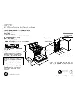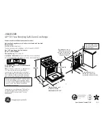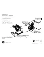
30" DUAL FUEL SLIDE-IN CONVECTION
SELF-CLEAN RANGE
229C4059P465
IMPORTANT SAFETY NOTICE: This information is intended for use by
individuals possessing adequate backgrounds of electrical, electronic and
mechanical experience. Any attempt to repair a major appliance may result in
personal injury and property damage. Neither the manufacturer nor the seller
can be responsible for the interpretation of this information or assume any
liability in connection with its use.
DISCONNECT POWER BEFORE SERVICING
IMPORTANT: RECONNECT ALL GROUNDING DEVICES. All parts of
this appliance capable of conducting electrical current are grounded.
If grounding wires, screws, straps, clips, nuts or washers used to
complete a path to ground are removed for service, they must be
returned to their original position and properly fastened.
GROUNDING SPECIFICATIONS
Ground Path Resistance 0.10
Ω
Max.
Insulation Resistance 250K
Ω
Min.
INSTALLATION REQUIREMENTS
Power Supply: This appliance must be supplied with proper voltage and
frequency, and connected to an individual, properly grounded branch circuit,
protected by a circuit breaker or time-delay fuse, as noted on rating plate.
Wiring
must conform to the National Electrical Codes. The rating plate is located on the lower
front frame above the storage drawer.
OVERCURRENT PROTECTION RANGES
208V
12.4
NEC
MAXIMUM KILOWATT
RATING
RATING
40 Amp
ATTENTION: This range connector
block is recognized for copper and
aluminum wires. Refer to the Installation
Instructions for additional details.
240V
16.0
IMPORTANT INSTALLATION INFORMATION
1.
This model is shipped with a filler strip. Please see installation instructions for use.
2.
L.P. Gas Conversion—Required information in installation instructions.
3.
After servicing, make sure the range leg levelers completely engage the
anti-tip bracket.
4.
Some vinyl wall tiles and floor coverings, as well as some indoor-outdoor
carpeting, soften at fairly low temperatures. If you are unsure of the heat
resistance of a material, put a protective covering under the range to prevent
possible heat damage during range use.
5.
Make sure the wall coverings, countertop and cabinets around the range can
withstand the heat (up to 194°F) generated by the range.
The cabinet must have solid sides and a solid back. The floor upon which
the range sits must be solid also. Any openings around the gas or electrical
outlets must be sealed. All cabinet openings must be sealed at the time of
installation to prevent drafts. Drafts will affect safe use of the oven.
SEALED SURFACE BURNER
RF
15,000
—
No. 49
RR
6,000
—
No. 56
LF
11,000
—
No. 52
LR
9,100
—
No. 54
BAKE
—
3.4
—
BROIL
—
3.6
—
CONVECTION
—
2.5
—
KW
BURNER
BTU RATE
BURNER OUTPUT RATING:
NATURAL GAS 4" W.C.P.
ORIF.
SIZE
REPAIR
PART
RF
13,000
—
No. 59
RR
6,000
—
No. 70
LF
9,100
—
No. 63
LR
8,000
—
No. 65
BAKE
—
3.4
—
BROIL
—
3.6
—
CONVECTION
—
2.5
—
KW
BURNER
BTU RATE
BURNER OUTPUT RATING:
L.P. (PROPANE) GAS 10" W.C.P.
ORIF.
SIZE
REPAIR
PART
SPARK
IGNITER
SPARK IGNITOR
MAINTOP BURNER ALIGNMENT
For proper operation of the burner, alignment of the orifice holder, orifice, and air/gas
mixer tube must be correct. The alignment can be checked by placing 7mm or 9/32"
nutdriver over the orifice to exaggerate the angle. The nutdriver should stand straight,
indicating the alignment and gas injection angle is correct. A slight downward pressure
may be necessary to seat the nutdriver over the “Orifice Retainer Ring”. If an angle
adjustment is necessary, remove the burner cap and head to inspect the orifice holder
and the brackets that hold them in place. Adjust as necessary.
A misaligned burner
may result in uneven flames around the burner head.
LOW FLAME SIMMER ADJUSTMENTS
Remove the surface control knob and locate the adjustment screw on the valve body at
about the 6 o’clock position.
NOTE: Low setting adjustments must be made with two other burners in operation
on a medium setting. This procedure prevents the simmer flame from being set too
low, resulting in the flame being extinguished when other burners are turned on.
MAINTOP REMOVAL AND ACCESS TO SPARK MODULE
1.
Cut off gas supply to range.
2.
Cut off electrical supply to range.
3.
Remove the control panel as follows:
a) Remove knobs.
b) Unscrew and remove hexagonal control panel fasteners.
c) Lift control panel glass and remove ribbon connector.
d) Remove hex head screws from metal insert.
e) Lift off insert / clock assembly.
f) Remove the 3 amp connectors from the electronic clock.
g) Disconnect the 12 pin amp connector.
h) Remove the upper hex head screws holding the control panel to the
maintop frame.
i) Remove the lower screws holding the control panel to the maintop baffle.
(NOTE: These are accessed through the top of the oven cavity behind the door.)
j) Remove the control panel.
4.
Remove the gas fitting (right side) connecting the gas manifold to the gas supply line.
5.
Remove two screws—one right, one left—holding the maintop to the range frame.
6.
Lift off the maintop by sliding forward.
NOTE:
Take care to miss the oven cavity vent
when sliding forward.
SURFACE BURNER ADJUSTMENTS
Standard adjustments to the air shutter and gas metering orifices are not possible on
sealed burners. If burner flames appear to be abnormal, check the following:
• Check gas pressure available to the burners. The required operating pressure is 4"
W.C.P. Natural Gas or 10" W.C.P. LP (Propane) Gas. The pressure reading can be
taken at the TOP burner orifices.
• Check for drafts entering the burner box from behind the range. Strong drafts beneath
the maintop can extinguish the burner and/or cause erratic burner flames.
• Check for blockage or partial blockage of the orifice. Inspect the orifice to be sure it
has been drilled on center and is free of debris or burrs.
• Check the burner alignment per the “Burner Alignment” section of this manual.
• If the flames blow and lift off the burner and the cause of the problem cannot be found,
installing an orifice with smaller diameter openings may solve the problem. In high
altitude (above 6000 ft.) installation, the orifices will usually have to be downsized.
Smaller orifices are available as listed below:
Smaller Orifices for Natural Gas:
Burner
RF
RR
LF
LR
Size
No. 51
No. 56
No. 53
No. 54
Part Number
WB28K10091
WB28K10085
WB28K10087
WB28T10017
Smaller Orifices for LP Gas:
Burner
RF
RR
LF
LR
Size
No. 60
No. 70
No. 64
No. 66
Part Number
WB28K10086
WB28K10085
WB28K10087
WB28T10017
TEST THE FLAME STABILITY
Test 1:
Turn the knob from “HI” to “LOW” quickly. If the low flame goes out, increase the
flame size and test again.
Test 2:
With the burner on “LOW” setting, open and close the oven door quickly. If the
flame is extinguished by the air currents created by the door movement, increase the
flame height and test again.
ACCESS TO CONTROL VALVE:
The control valve for this product is not front serviceable. There is a test loop available
through the control panel that will allow a check of amperage to verify continuity. The
amperage should be between 3.4 & 3.6 at 116±1 volts.
IN CASE THE CONTROL VALVE NEEDS REPLACING, FOLLOW THESE STEPS:
1.
Shut off the gas to the range.
2.
Shut off power to the range.
3.
Pull range out from the cabinet to expose the control valve.
Reverse the steps for repositioning.
NOTE:
Make sure the anti-tip bracket is installed correctly when pushing the range
back into place.
RANGE GAS SHUT-OFF VALVE
The gas shut-off valve is located on the side
of the pressure regulator which is mounted to
the back of the range. Access to the shut-off
lever is obtained by removing the storage
drawer and reaching through the opening on
the right side of the control box.
ELECTRONIC OVEN CONTROL (HP)
CAUTION:
Components are electrically
HOT
on control when voltage is connected
to range.
The Electronic Oven Control system consists of the control, key panel, oven sensor,
door and lock assembly. The key panel (control panel) and electronic control are
separate components but must be tested together.
See section on sensor and lock switch connector
KEY PANEL TEST
Press each pad on the key panel followed by the start pad. If the key panel is functioning
properly, the following should occur:
•
BAKE, BROIL, CONVECTION BAKE, CONVECTION ROAST, CLEAN, TIMER, CLOCK,
STOP TIME, COOK TIME, PROOF, PROBE
and
RANGE LOCKOUT
Modes – Audible
tone plus display showing mode of operation selected.
•
CLEAR/OFF
– Audible tone and display shows time of day.
•
PROBE
– Audible tone and response if meat probe is plugged in.
•
Numerical Pads
– Audible tone. Can only be used after another function has been selected.
RELAY CONTACTS OPERATION TEST AND CONTROL VOLTAGE CHECK
L1-N
COM to N
L1-BA-DLD
*Light-L1
COM to MDL
L1 to CF
TERMINALS
CIRCUIT TERMINALS OHMS
120 VAC ALL THE TIME.
120 VAC ALL THE TIME.
240 VOLTS when oven is not
calling for heat (BAKE, CONV.
and BROIL relay contacts open).
120 VOLTS when light is on.
120 VOLTS not locking or
unlocking, door closed.
120 VOLTS when oven door is
closed and Conv. Bake and
Conv. Roast not operating.
VOLTAGE
*If oven light is not working,
make the following checks:
• Check oven light bulb.
• Light is to come on when
door is opened—check
voltage across light socket
terminals. It should read
120 VAC. If 0 volts, check
jamb switch and wiring.
• Light is to come on when
control light pad is pressed.
RLY105 should click. Check
voltage from P104-7 to L1.
It should read 120 VAC.
If 0 volts, check oven light
keypad using ohmmeter test.
If keypad is good, replace the
control.
Oven sensor
Temp.
Door
Unlatched
Door Latched
6 to 8
3 to 5
4 to 5
4 to 5
3 to 5
1100
Ω
@ Rm
2650
Ω
@ 865°F
0
Ω
open
0
Ω
open
OVEN SENSOR AND DOOR SWITCH OHMMETER TEST
(See “Motorized Door Lock Operation” for door switch function explanation.)
Remove
power from oven. Make resistance measurement from side of sensor and lock
switch connector, with exposed terminals disconnected from control.
OVEN SENSOR AND LOCK SWITCH CONNECTOR
BAKE
RELAY
BAKE
L1
"L1"
BLACK
BROIL
RELAY
L1
BROIL
*Approximately 25% on time in Bake.
Bake & Broil relays cannot be on at same time.
There is approx. 1 min. of dead time between
bake and broil unit operation after preheat.
Bake and broil units operate sequentially during first
(preheat) cycle.
** 1 second dead time between bake and broil
units while calling for heat in clean.
"L2"
RED
"L1"
BLACK
L1
BROIL
"L2"
RED
BROIL
RELAY
2700W/16.8
3600 W / 16
BAKE & TIME BAKE*,
BROIL & CLEAN-UNTIL
AFTER 750˚F IS REACHED
3600W/16.4
14.2A
15A
15A
BK
BR
BR
DLB
RELAY
DLB
RELAY
**If convection fan is not working, make the
following checks:
• Check the voltage from terminal CF to N on
control—it should read 120V in Conv Bake
or Roast mode. If not, replace the control.
• If voltage is OK, check the convection fan
motor. It reads approximately 15–20
Ω
at
room temperature. Check to make sure the
fan shaft is not rubbing on the oven liner.
1
2
3
4
5
6
7
8
OVEN TEMP SENSOR
1100
Ω
@ ROOM TEMP
2650
Ω
@ CLEAN TEMP
UNLOCK
SW 2
MEAT PROBE*
50K @ RM
CONTROL
CONNECTOR
PLUG
THERMAL SWITCH (BAKE)
OPEN @169˚F
CLOSES @140˚F
1
1
THERMAL SWITCH
OPEN @240˚F
CLOSES @190˚F
2
2
L2
L1
L-1
CONVECTION
BAKE ELE.
2500W
CONVECTION BAKE
240V.
10.4A
10.4A
CONV-1
DLB
RELAY
N
L1-1
DOOR
SW
NO
C
CONVEC
M
CONVECTION
FAN
CW
CCW
BROIL-1
L2
L1
N
L-1
L1-1
DOOR
SW
BROIL
4000W
14.4A
CONVECTION ROAST
NO
C
240V.
15A
15A
CONVEC
DLB
RELAY
M
CONVECTION
FAN
CW
CCW
NOTE: Installation information for reference
only. See Installation Instructions shipped
with product for complete details and before
attempting to install.
Anti-tip bracket must be attached to the floor or
wall to hold either right or left rear leg leveler.
Make sure leg leveler reengages the bracket
when range is moved for any reason.
WARNING
• All ranges can tip
• Injury to persons could result
• Install anti-tip bracket
packed with range
• See Installation Instructions
Adjacent Cabinet
Or Final Location
Of Range Side Panel
Wall
Floor-Wood
Bracket
Side
Rear
Leveling
Leg
Floor-Concrete
FLOOR–CONCRETE
FLOOR–WOOD
Wall
Adjacent Cabinet
or Final Location of
Range Side Panel
Bracket Side
Rear
Leveling Leg
Attachment To Wall
Bracket
Wall
Plate
Screw Must
Enter Wood
Or Metal
Attachment to Wall
Bracket
Wall Plate
Screw Must
Enter Wood
or Metal
To Replace:
1.
Firmly grasp both sides of the door at
the top.
2.
With the door at the same angle as the
removal position, seat the indentation of the
hinge arm into the bottom edge of the hinge
slot. The notch in the hinge arm must be fully
seated into the bottom of the slot.
Removal position
Push hinge locks up to lock
3.
Fully open the door. If the door will not fully open, the
indentation is not seated correctly in the bottom edge
of the slot.
4.
Push the hinge locks up against the front frame of
the oven cavity, to the locked position.
5.
Close the oven door.
4.
Close door to the door removal position, which is halfway
between the broil stop position and fully closed.
5.
Lift door up until the hinge arm is clear of the slot.
Bottom Edge
of Slot
Hinge Arm
Indentation
Hinge Arm
Hinge
Lock
REMOVABLE OVEN DOOR
The door is very heavy. Be careful when removing
and lifting the door. Do not lift the door by the handle.
To Remove:
1.
Fully open the door.
2.
Push the hinge locks down toward the door frame,
to the unlocked position. A tool, such as a small
flat-blade screwdriver, may be required.
3.
Firmly grasp both sides of the door at the top.
Slot
Hinge Lock
Pull hinge locks down to unlock
Gas In
let
Gas Supply to
Top Burner
Pressure Regulator
as seen from Front of
Range
Burner
Grate
Burner
Base
Burner
Cap
Burner
Head
Spark Igniter
Glass
Maintop
Spark
Ignitor


