GE Pro Elite 268-716-150-1248 Operation Manual Download Page 12

12

Drain Line Connection

Note: Standard commercial practices are expressed 

here. Local codes may require changes to the following 

suggestions. Check with local authorities before 

installing a water conditioning system.

1.  The unit should be above and not more than 20 feet 

(6.1 m) from the drain. Use an appropriate adapter 

fitting to connect 1/2-inch (1.3 cm) plastic tubing to 

the drain line connection of the control valve.

2.  If the backwash flow rate exceeds 5 gpm (22.7 Lpm) 

or if the unit is located 20-40 feet (6.1 – 12.2 m) from 

drain, use 3/4-inch (1.9 cm) tubing. Use appropriate 

fittings to connect the 3/4-inch tubing to the 3/4-inch 

NPT drain connection on valve.

3.  The drain line may be elevated up to 6 feet (1.8 m) 

provided the run does not exceed 15 feet (4.6 m) and 

water pressure at the conditioner is not less than 40 

psi (2.76 bar). Elevation can increase by 2 feet (61 cm) 

for each additional 10-psi (.69 bar) of water pressure 

at the drain connector.

4.  When the drain line is elevated but empties into a 

drain below the level of the control valve, form a 

7-inch (18 cm) loop at the far end of the line so that 

the bottom of the loop is level with the drain line 

connection. This will provide an adequate siphon trap. 

Tie or wire the hose in place at the drain point. Also 

provide an air gap of at least 1-1/2 inch between the 

end of the hose and the drain point.

5.  When the drain empties into an overhead sewer line, a 

sink-type trap must be used.

6.  Secure the end of the drain line to prevent it from 

moving.

Figure 9  Drain Line Connection


WARNING: Never insert drain line directly 

into a drain, sewer line or trap (Figure 

9). Always allow an air gap between the 

drain line and the wastewater to prevent 

the possibility of sewage being back-

siphoned into the conditioner.

Regenerant Line Connections

The regenerant line from the brine tank safety brine valve 

(Figure 11) connects to the valve. Make sure both safety 

valve tube fittings are tight. Make the connections and 

hand tighten.

Note: Be sure that the regenerant line is secure and 

free from air leaks. Even a small leak may cause the 

regenerant line to drain out, and the conditioner will not 

draw regenerant from the tank. This may also introduce 

air into the valve causing problems with valve operation.

Ensure that plumber tape pipe sealant is applied to the 

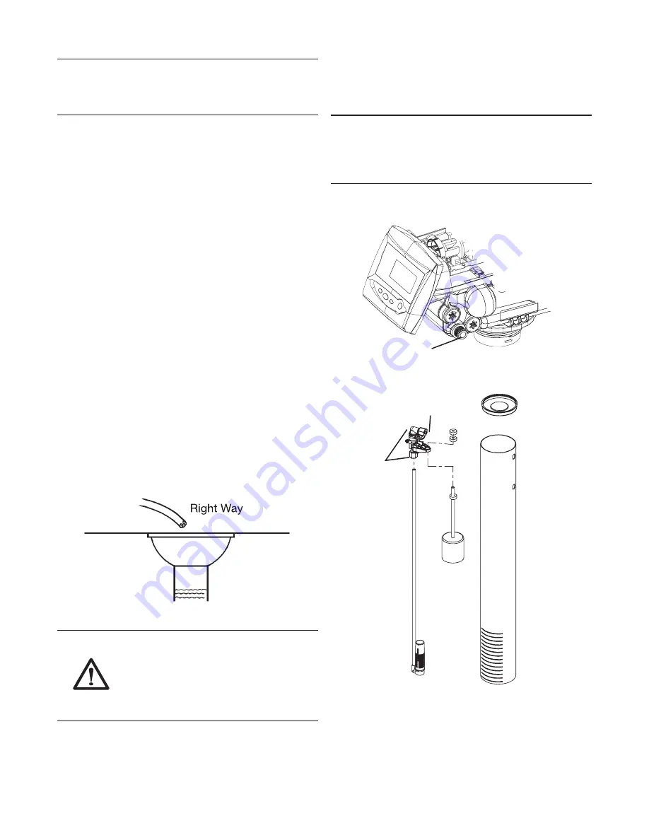
3/8-inch NPT regenerant line connection (Figure 10).

Regenerant Line Connection

Figure 10  


Regenerant Line Connection

Figure 11  Salt Tank Safety Brine Valve and  

Brine Well Assembly

Tube Fitting

Summary of Contents for Pro Elite 268-716-150-1248

Page 1: ...Pro Elite Professional Series Water Treatment System by GE Operation Manual Pro Elite Analyzer...

Page 2: ...Cursors 17 Button Functions 17 Programming Overview 18 Analyzer Control Operation 18 Level I Programming 18 Level l Programming Analyzer Conditioner 19 Level II Programming P Values 20 Programming the...

Page 3: ...d to minimize the amount of regenerant brine and water used in its operation Efficiency rated water softeners shall have a rated salt efficiency of not less that 3350 grains of total hardness exchange...

Page 4: ...ghtened plumber tape may be used on connections that do not use an O ring seal Do not use pipe dope type sealants on the valve body Do not use pliers or pipe wrenches Do not use petroleum based lubric...

Page 5: ...x 36 48 3 x 91 5 cm 19 x 36 48 3 x 91 5 cm Salt Storage 240 lbs 109 kg 240 lbs 109 kg 240 lbs 109 kg Drain Water Rate 2 7 gpm 10 2 L m 3 9 gpm 14 7 L m 3 9 gpm 14 7 L m Service Connection Size 1 NPT 1...

Page 6: ...conditioner be installed in a protected environment When installing the water conditioning system outdoors several items must be considered Moisture The valve and control are rated for NEMA 3 locatio...

Page 7: ...nism 3 Jacket Resin Tank 11 Tank Collar 4 Base 12 Riser Tube 5 268 Logix PE Valve w 716 Control 13 Upper Basket 6 Resin Tank 14 Cover 7 Door Access Sensor 15 Shield 8 Sensors Wired Probes Brine Tank 1...

Page 8: ...8 Equipment Installation Dimensions 36 9 938 1 60 7 1541 6 28 2 715 9 32 2 817 5 53 4 1356 6 55 1398 1 5 0 127 2 5 63 5...

Page 9: ...Floor Drain Figure 1 Standard Basement Before Installation Cold water lines shown Soft Water Hard Water Outside Faucet Outside Faucet Bath Tub Lavatory Toilet Kitchen Laundry Tubs Pump or Meter Hot W...

Page 10: ...y the cover aside for now To Assemble the Media Tank 1 If the floor under the media tank is uneven the leveling feet may be installed Slowly lay the tank on its side Press or tap the feet into the poc...

Page 11: ...B Y P A S S B Y P A S S Water Conditioner Water Conditioner In Out In Out Figure 7 Model 1265 Bypass Included Water Conditioner Water Conditioner Water Conditioner Water Conditioner Normal Operation I...

Page 12: ...drain line connection This will provide an adequate siphon trap Tie or wire the hose in place at the drain point Also provide an air gap of at least 1 1 2 inch between the end of the hose and the drai...

Page 13: ...ure hose in place Drain Air Gap Figure 12 Electrical Connection Note There are no user serviceable parts in the AC adapter motor or the control board The Analyzer control operates on a 12 volt alterna...

Page 14: ...enerant draw is completed when the air check closes Slow Rinse Downflow Cycle C3 Water flow moves the regenerant through the resin at a specific rate and rinses to the drain The resin is regenerated R...

Page 15: ...optical sensor which is rotated approximately 90 degrees out of phase Note If electrical power is not available the camshaft can be rotated counterclockwise by hand if the motor is removed Cycle Indic...

Page 16: ...sed such as those sold for commercial laundries adjust the dosage accordingly 1 Dosage Polystyrene resin 1 2 fluid ounce 35 5 mL per cubic foot Non resinous exchangers 0 8 fluid ounce 23 7 mL per cubi...

Page 17: ...as a solid icon during regeneration 12 When hourglass is flashing this indicates that the control is moving to a regeneration cycle Appears as a solid icon during a cancelled regeneration and the cont...

Page 18: ...formation in memory for 8 to 24 hours depending on the installation If the super capacitor is exhausted the Analyzer control will display four dashes immediately upon power up The Time of Day and Day...

Page 19: ...ress then or press press then PM Cubic feet 1 0 to 2 0 Lbs ft 3 Time Day Regeneration Time Day Time Day Regeneration Time Day Time Day Regeneration Time Day Time Day Regeneration Time Day Time Day Reg...

Page 20: ...lt Setting 3 18 50 290 1 10 9 110 Lbs Cu ft3 g L Set in Level I Programming P7 Capacity View Only 1 140 0 1 14 0 1 0 1 Calculated Kilograins Kilograms Values dependent on P9 setting P8 Not Used P9 Uni...

Page 21: ...Flow rate dictated by size of drain line flow controller C2 Regenerant Draw Not Adjustable 1 Min See Notes Automatically calculated from resin volume and salt dosage settings C3 Slow Rinse 0 200 1 Min...

Page 22: ...n for three seconds while H4 number of regenerations since last reset is being displayed will reset the numbers stored in H4 H5 H6 H7 and H8 Holding the set key down for three seconds while H9 months...

Page 23: ...rol reaches the backwash cycle the hourglass is no longer displayed and the motor will turn off Pressing the SET button will display the time remaining for the current cycle 4 Fill the media tank with...

Page 24: ...h the control in the treated water position press and hold the REGEN button on the control for five seconds This will initiate a manual regeneration The control will display an hourglass indicating th...

Page 25: ...her regeneration Advance the controller to the brine refill position C8 to prime the line between the regenerant tank and the valve conditioner only A Slowly open the main water supply valve again to...

Page 26: ...immediate manual regeneration A solid regeneration icon will be displayed The control will immediately begin a regeneration Delayed Second Regeneration Pressing and releasing the REGEN button while th...

Page 27: ...27 Pro Elite Valve Exploded View and Parts List BYPASS BYPASS 20 21 22 23 24 1 2 3 4 5 6 7 8 9 10 12 13 14 15 16 17 18 19 11 12...

Page 28: ...18 1010154 O Ring Tank 1 4000585 Skirt Pro Elite Lt Gray 1 19 1232370 O Ring Riser Tube 1 8 1000811 Transformer 120 VAC 60 Hz N American Plug 1 20 4001033 Probe Cable Clips Kit 1 9 3019221 Motor Optic...

Page 29: ...29 19 21 22 23 24 25 2 3 4 5 6 7 9 10 12 13 14 15 16 17 18 11 Conditioner Tank and Regenerant Tank Assembly Exploded View and Parts List 1 A A A 26 20 8 27 28 5 26 29...

Page 30: ...tton GE Logo 1 4 1 26 1234170 Screw 8 18 x 9 16 Type 25 4 10 4000347 Cover Brine Tank Pro Elite 1 27 4001265 Washer Countersunk Finishing SS 4 11 4000348 Collar Brine Tank Pro Elite 1 28 4001266 Screw...

Page 31: ...CH15024 Cap Brine Well 4 Dia Caplug STP 4 1 6 60068 8 06 Brine Float w One Grommet As Purchased 1 7 60002 27 Air Check Assembly 1 8 BR10332 Tubing Insert Brass 2 CH20774 Overflow Fitting Assembly 1 CH...

Page 32: ...ical sensor is connected and in place Verify that motor gear has engaged cam gear If everything is connected try replacing in this order 1 Wire harness motor optical sensor assembly 2 Control Camshaft...

Page 33: ...ing to instructions b Remove restriction c Clean injector and screen d Replace injector and cap Contact dealer e Remove foreign matter from disc and check disc for closing by pushing in on stem Replac...

Page 34: ...Pentair Residential Filtration LLC 5730 North Glen Park Road Milwaukee WI 53209 4454 USA 262 238 4400 Phone 262 238 4402 Fax 2011 Pentair Residential Filtration LLC P N 4001051 Rev D MR14...

Reviews: