


GE Healthcare
Direction 5743854-1EN, Revision 1 Optima XR642/XR648 Pre-Installation
Chapter 2 - Equipment
Page 47
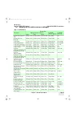
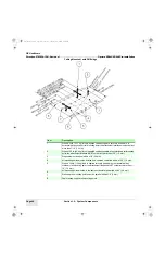
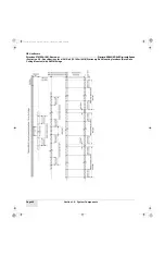
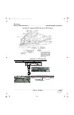
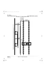
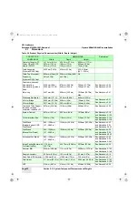
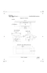
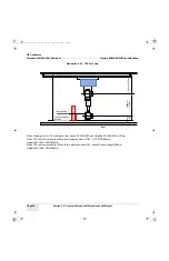
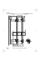
Illustration 2-7 : Specifications for a Typical 4064mm (13’- 4") Stationary Rail Mounting Interface (Both Rails
Ceiling Mounted) with 3M Bridge
Item
Description
1
When a 50 lb. (22.7 kg) force is applied vertically upward, vertically downward, or
horizontally at any support rail mounting point, the attachment interface must not deflect
more than 1/16” (1.5 mm).
2
When a 100 lb. (45.4 kg) force is applied vertically upward at any stationary rail mounting
point, the attachment interface MUST not deflect more than 1/16” (1.5 mm).
3
Diagonals must be equal within ±1/4” (6.5 mm).
4
All mounting points must be located on a common centerline within ±1/16” (1.5 mm).
5
When a 300 lb. (136 kg) load is applied vertically downward or horizontally at any
stationary rail mounting point, the attachment interface MUST not deflect more than 1/
16” (1.5 mm).
6
All mounting points must be in the same horizontal plane within ±3/32” (2.4 mm)
7
Stationary rail mounting points must be parallel within ±1/8” (3 mm)
8
Cable takeup support rail mounting points
Pre-Install.book Page 47 Tuesday, January 30, 2018 2:36 PM