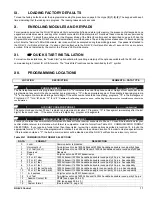
SLOW COMMUNICATOR FORMAT CODES
20
NX-4V2 Control
46
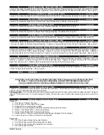
AUXILIARY OUTPUT 1 - 2 SPECIAL TIMING
2 ............ feature select
Location 46 contains special timing feature activation for the four auxiliary outputs. Segment 1 corresponds to output 1; Segment 2
corresponds to output 2.
Segments 1 - 2:
1 = On if output should be timed in minutes; Off if timed in seconds.
2 = On if output should latch; Off if output should be timed.
3 = On if output should stop timing upon code entry; Off if the output should continue to time upon code entry.
4 = On if output should only activate between the closing and opening time in loc. 52 and 53.
5 = On if output should only activate between the opening and closing time in loc. 52 and 53.
6 = On if output should be inverted (0 volts going to 12 volts when activated).
7 = Reserved.
8 = Reserved.
47
AUXILIARY OUTPUT 1, EVENT & TIME
2 ............ numerical
Segment 1:
Use Table XIII-1 to select the event that will activate Auxiliary Output 1.
Segment 2:
Program the timing from 0-255 (minutes or seconds, depending on data programmed in Segment 1, Location 46).
Programming a "0" makes the output follow the event.
48
AUXILIARY OUTPUT 2, EVENT & TIME
2 ............ numerical
Segment 1:
Use Table XIII-1 to select the event that will activate Auxiliary Output 2.
Segment 2:
Program the timing from 0-255 (minutes or seconds, depending on data programmed in Segment 2, Location 46).
Programming a "0" makes the output follow the event.
49 - 50
RESERVED
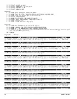
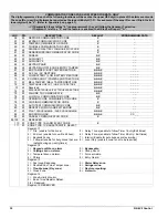
Table XIII-1 AUXILIARY OUTPUT EVENT SELECTION
DATA
EVENT
DATA
EVENT
DATA
EVENT
0
/
Burglary Alarm
19
Exit
38
Download In Process
1
/
Fire Alarm
20
Entry or Exit
39
Smoke Power
2
/
24 Hour Alarm
21
Armed State
40
Short Circuit (Over-current)
3
/
Trouble Alarm
22
Disarmed State
41
Box Tamper
4
/
Tamper Alarm
23
Ready
42
Siren Tamper
5
Yelping Siren (Burglary)
24
Not Ready
43
Any Open
6
Temporal Siren (Fire)
25
Fire
44
Any Short
7
Any Siren
26
Fire Trouble
45
Any Fault (Open/ Short on Non-Fire Zone)
8
Any
Bypass
27
Chime
46
/
Any
Alarm
9
AC Fail
28
/
Expander Trouble
47
Beeping Keypad
10
Low Battery
29
Dynamic Battery Test Time
48
/
Code Entry (See note below)
11
/
Duress
30
Open
Period
49
˜ /
Key FOB Function 1
12
/
Aux 1 Keypad Zone
31
Closed Period
50
˜ /
Key FOB Function 2
13
/
Aux 2 Keypad Zone
32
Listen-In
51
Always ON
14
/
Panic Keypad Zone
33
Line Seizure
52
Alarm Flash
15
Keypad Tamper
34
Ground Start
53
Armed Away
16
/
Autotest
35
Fail To Communicate
54
Armed Stay
17
Alarm Memory
36
Telephone Line Fault
55
Aux Comm Fail
18
Entry
37
Program Mode
56
(CP-01) Progress Annunciation
˜
Events 49 & 50 require one or more of the following to operate: NX-408E, NX-416E, NX-448E wireless receivers, or NX-1700E card reader
/
If set to follow condition, these events will be 1 second.
Note:
When Event 48 is programmed, it is possible to program a user code's authorization to select which output(s) a particular code will activate.
When LED 8 is on for an authorization, then LEDs 1- 2 correspond to that code activating outputs 1 - 2 respectively.
(See programming the
LED keypads on page 7.)
L
51 AUTOTEST
CONTROL
4 ............ numerical
Segment 1:
Program a "1" if the interval is to be in hours; Program a "0" if in days. Add a
A
2" to suppress the daily test or a
A
3" to
suppress the hourly test if any report has been sent.
Segment 2:
Program the Autotest interval from 1-255 hours/days.
Segment 3:
Program the Autotest report hour in 24-hour format (if the interval is in hours, this segment is ignored).
Segment 4:
Program the Autotest report time, number of minutes after the hour.
WWW.DIYALARMFORUM.COM


