


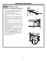
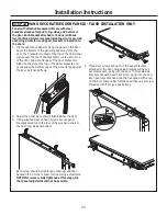
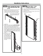


• Gently pull back at the ends of the plastic straps to make
the channel rest flush behind the wall.
• Hold the ends of the straps in one hand and slide the plas-
tic cap along the straps until the flange of the cap is flush
with the wall.
• Place your thumb between the plastic straps and bend up
and down to snap the straps off at the wall.
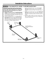
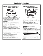
Install Screws and Bolts:
• Have someone hold the wall bracket centered in place
with each of the holes aligned with the correct opening in
the bracket and level with the horizontal line.
• Insert the lag screws through the bracket and into the
stud. Tighten with a wrench.
•
Insert the bolts into the toggle by hand until snug.
Tighten with a wrench.
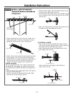
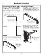
Anti-Tip Wall Bracket
Bolt
Wall Toggle
Drywall or
Steel Stud
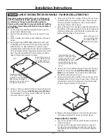
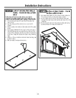
• Mark an additional hole at each end of the bracket. If one
of the studs is closer to the end of the bracket, mark an
additional hole towards the center of the bracket.
• Drill 1/2” holes into the wall board at the locations marked
for the toggles to be mounted (not the stud markings).
• Drill 3/16” holes into wooden studs where marked. If steel
stud construction, drill 1/2” holes into the studs where
marked. You will use 2 toggles with the metal studs.
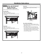
Install Wall Toggles:
The wall toggles and bolts can be ordered as Service Kit
#WR49X10193. Wall toggles are installed in the drywall
and metal studs for stability. Install the wall toggles as fol-
lows:
• Drill 1/2” holes at the wall markings made in the holes at
the ends of the wall bracket.
• Hold the metal channel flat against the plastic straps
and slide the channel through the hole.
Installation Instructions
18
Plastic Straps
Metal Channel
Wood Stud
Lag Screw
Anti-Tip Wall Bracket
Two Additional
Hole Locations at
Ends of Brackets
Center
Wall Bracket
Line On Wall
Wall Studs
Line on Wall
Center
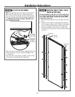
Cap
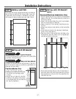
STEP 5 INSTALL ANTI-TIP BRACKET
(Standard/Stainless Installation
only) (cont.)
Summary of Contents for Monogram ZIRS360NNLH
Page 30: ...Notes 30...
Page 31: ...Notes 31...