background image

GE HealthCare CONFIDENTIAL

D

IRECTION


5936427

, R

EV

. 1

LOGIQ T

OTUS


Basic Service Manual

Section 8-7 - Replacing OPIO

8 - 109

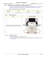
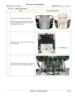
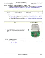
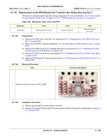
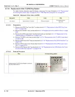
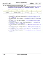
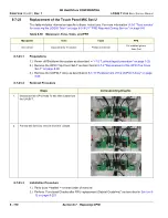
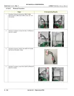
8-7-18 Replacement of the OPIO Button Set-T and the User Define Key Cap Set-T

This table includes information specific to these instructions. For more information  

8-2-6 "Tools needed 

for servicing the LOGIQ Totus" on page 8-5

 /

8-2-7 "PPE Required During Service" on page 8-6

8-7-18-1

Preparations

1.) Remove the OPIO Top Cover Set-T as described in 

8-7-2 "Replacement of the OPIO Top Cover 

Set-T" on page 8-89

2.) Remove the UOPIO-T Assy as described in 

8-7-10 "Replacement of the UOPIO-T Assy" on page 

8-98

3.) Remove the OPIO Laser Color Trackball with Cable as described in 

8-7-11 "Replacement of the 

Trackball assy-U_FLT20UFA-GJ" on page 8-101

4.) Remove T2 OPIO Lower Assy as described in 

8-7-14 "Replacement of the T2 OPIO Lower Assy" 

on page 8-104

5.) Remove OPIO Knob Set-T Assy as described in 

8-7-16 "Replacement of the OPIO Knob Set-T" on 

page 8-106

8-7-18-2

Removal Procedure

8-7-18-3

Installation Procedure

1.) Parts to be installed in reverse order of removal
2.) Perform “Functional Checks after FRU replacement (Debrief Guideline)” as described in 

Section 8-

12 on page 8-223

Table 8-54   Manpower, Time, Tools, and PPE

Manpower

Time

Tools

PPE

One person

Approximately 15 minutes

Philips Screwdriver

Cut resistant gloves

Knee Pad

Step

Corresponding graphic

1.

Remove the buttons from the OPIO LOWER

Summary of Contents for LOGIQ Totus

Page 1: ...LOGIQ Totus Basic Service Manual 5936427 Rev 1 ADVANCED SERVICE DOCUMENTATION 2023 GE HealthCare GE HealthCare CONFIDENTIAL UNLICENSED USE BY NON GE HealthCare PARTIES IS STRICTLY PROHIBITED...

Page 2: ......

Page 3: ...GE HealthCare CONFIDENTIAL Direction 5936427 Rev 1 LOGIQ Totus Basic Service Manual i Important Precautions TTRANSLATION POLICY...

Page 4: ...GE HealthCare CONFIDENTIAL Direction 5936427 Rev 1 LOGIQ Totus Basic Service Manual ii...

Page 5: ...GE HealthCare CONFIDENTIAL Direction 5936427 Rev 1 LOGIQ Totus Basic Service Manual iii...

Page 6: ...GE HealthCare CONFIDENTIAL Direction 5936427 Rev 1 LOGIQ Totus Basic Service Manual iv...

Page 7: ...HealthCare equipment shall only utilize qualified personnel i e GE HealthCare s field engineers personnel of third party service companies with equivalent training or licensed electricians to perform...

Page 8: ...ealthCare to use this proprietary software you are authorized to use this Material according to the conditions stated in your license agreement However you do not have the permission of GE HealthCare...

Page 9: ...n Date Reason for change Rev 1 August 2023 Initial release Chapter Revision Chapter Revision Chapter Revision Title Page Rev 1 Chapter 4 Rev 1 Chapter 10 Rev 1 Warnings Rev 1 Chapter 5 Rev 1 Index Rev...

Page 10: ...GE HealthCare CONFIDENTIAL Direction 5936427 Rev 1 LOGIQ Totus Basic Service Manual viii This page was intentionally left blank...

Page 11: ...n this manual 1 4 Important Conventions 1 10 Conventions used in book 1 10 Standard hazard icons 1 11 Labels Icons on the system 1 13 Label Location 1 13 Safety Considerations 1 14 Introduction 1 14 H...

Page 12: ...GE HealthCare CONFIDENTIAL DIRECTION 5936427 REV 1 LOGIQ TOTUS BASIC SERVICE MANUAL x Table of Contents Customer Assistance 1 32 Contact information 1 32 Ultrasound system manufacturer 1 33...

Page 13: ...Q Totus Requirements 2 2 LOGIQ Totus environmental requirements 2 2 Electrical requirements 2 4 EMI limitations 2 6 Probe environmental requirements 2 8 Time and manpower requirements 2 8 Facility Nee...

Page 14: ...8 Unpacking the LOGIQ Totus 3 9 Packing Materials Recycling Information 3 10 Preparing for Setup 3 11 Verify Customer Order 3 11 Physical Inspection 3 11 Location of Multi Caution label and rating lab...

Page 15: ...ripherals peripheral connection 3 34 Barcode reader 3 35 Magstripe card reader 3 36 LAN Protection Cable Option 3 37 Network printers 3 38 Setting Up Connectivity and Tips 3 39 Navigating Connection M...

Page 16: ...rd functional checks 4 16 Footswitch functional checks 4 16 Basic control functional checks 4 17 Probe connector functional checks 4 18 B Mode functional checks 4 19 M Mode functional checks 4 21 Syst...

Page 17: ...e CONFIDENTIAL DIRECTION 5936427 REV 1 LOGIQ TOTUS BASIC SERVICE MANUAL Table of Contents xv Battery Pack Extended functional checks 4 29 Shear Wave Elastography Shear Elasto functional checks 4 30 Si...

Page 18: ...are 5 7 Electronic media 5 8 Advanced Information Option key structure 5 8 Advanced Information File structure 5 9 Advanced Information Logging 5 12 Advanced Information Encryption 5 13 Log file conte...

Page 19: ...ription 5 30 Purpose of this section 5 30 Power Supply Distribution 5 31 Cable Connection UBE T OPIO 5 33 Air Flow Distribution 5 34 Air Flow Distribution 5 34 Options and Peripherals Description 5 35...

Page 20: ...to monitor adjustments 6 3 Monitor adjustments 6 4 Advanced monitor adjustments 6 6 Monitor Arm and or Monitor Range of Motion Adjustment 6 10 Purpose of this section 6 10 Monitor and Monitor arm 6 10...

Page 21: ...ptive mode 7 11 Color statuses 7 11 Service Classes 7 12 Home 7 15 DICOM 7 22 Utilities 7 26 Options 7 41 Agent Configuration 7 42 Software Maintenance 7 45 Electromagnetic Interference EMI Troublesho...

Page 22: ...os DS 7 56 Device Management Device Mgmt 7 57 Probes Troubleshooting 7 70 Probe recognition 7 70 IC RIC5 9 CHI M Mode too dark 7 70 ML6 15 breast B and color flow zipper artifact 7 70 Body pattern pro...

Page 23: ...all images 8 9 Backing up the Patient Archive and System Configurations 8 9 Overview of the Base Image and Application Software 8 10 Loading the base image and application software full load 8 11 Loa...

Page 24: ...ement of the Probe Holder Rubber Set T 8 92 Replacement of the OPIO Handle Cover Set T 8 93 Replacement of the T2 OPIO Base Rear Cover Assy 8 95 Replacement of the Unity Gel Warmer Cable Cover 8 96 Re...

Page 25: ...r Cover Top Assy U 8 143 Replacement of the Rear Cover Bottom Assy T 8 144 Replacement of the Top Cover Assy T 8 145 Replacement of the Rear Cover Top L R Set U 8 146 Replacement of the T2 Handle 8 14...

Page 26: ...8 200 Replacement of the BW printer Option Cable Set U 8 201 Replacement of the Battery Option Cable Set U 8 204 Replacement of the U DCWD Set 8 206 Replacement of the UECG Assy 8 208 Replacement of t...

Page 27: ...board 8 225 Replacement of the A N Keyboard Latch Set T 8 225 Replacement of the OPIO Handle Cover Set T 8 225 Replacement of the T2 OPIO Base Rear Cover Assy 8 225 Replacement of the Unity Gel Warmer...

Page 28: ...of the UCO T Assy 8 234 Replacement of the Unity ACDC Assy 8 234 Replacement of the UHUB T 8 234 Replacement of the Touch Panel MIC Set U 8 235 Replacement of the Speaker Set U 8 235 Replacement of t...

Page 29: ...ment of the HDU 23 8 inch Monitor LOGIQ Exx 8 241 Replacement of the OPIO HUB To Monitor Power Cable 8 241 Replacement of the OPIO HUB To Monitor USB 2 0 Cable 8 241 Replacement of the UBE To Monitor...

Page 30: ...Parts Overview 9 1 Purpose of this chapter 9 1 Contents in this chapter 9 1 List of Abbreviations 9 2 Parts List Groups 9 3 LOGIQ Totus Model 9 4 Monitor and Monitor Arm 9 5 OPIO 9 7 Main Console 9 1...

Page 31: ...s and equipment 10 8 Specific requirements for care and maintenance 10 9 Functional checks 10 9 System functional checks 10 10 Peripheral option checks 10 11 Mains cable inspection 10 11 Optional diag...

Page 32: ...L xxx Table of Contents Type BF Patient Leakage current Mains to Probe 10 32 When There s Too Much Leakage Current 10 33 Earth and or Enclosure Fails 10 33 Probe Fails 10 33 Peripheral Fails 10 33 Sti...

Page 33: ...he information presented here before installing or servicing the LOGIQ Totus NOTE The information in this Service Manual is applicable to LOGIQ Totus 1 1 2 Contents in this chapter 1 1 Overview 1 1 1...

Page 34: ...on 1 2 1 2 2 Contents in this service manual 1 3 1 2 3 Typical users of LOGIQ Totus documentation 1 4 1 2 4 LOGIQ Totus models covered in this manual 1 4 1 2 4 1 LOGIQ Totus Options 1 5 1 2 1 Attentio...

Page 35: ...tus 3 LOGIQ Totus Setup Contains setup procedure with procedure checklist 4 Functional Checks Contains functional checks that must be performed as part of the installation or as required during servic...

Page 36: ...n on how to change the LOGIQ Totus s date can be found in Chapter 10 Customizing Your System of the LOGIQ Totus User Manual Typical users of the Basic Service Manual Service personnel setup maintenanc...

Page 37: ...Cardiac AFI O Report Writer O TVI O Auto EF O Stress Echo O Trice O LOGIQ Apps O Scan Assistant O AUTO IMT O B Steer O B FLOW O FLOW QA O Measure Assist Breast O Measure Assist OB O ELASTOGRAPHY O EL...

Page 38: ...O 4D O WirelessLAN O CW O VScan Air O Hardware Options Peripherals Accessories CW Doppler O Realtime 4D O Scan on Battery 3 pack O Scan on Battery 6 pack O WiFi Bluetooth Module O USB WiFi Dongle O P...

Page 39: ...HOOK O Drawer O Barcode Reader USBee1000A O Magnetic Card Reader O Powervar144k120v MG UPS O Powervar144k 230V MG UPS O Ultrasound Probe Rack O Ethernet Protection Cable O Gel Warmer O SONY UPD25MD C...

Page 40: ...6Tc RS Probe O TEE RS DLP Adapter O C2 7 D Probe O C2 7VN D Probe O C2 7D LC Probe O P2D Probe O RIC5 9 D 4D Probe O RAB6 D Probe O P6D Probe O BE9CS D Probe O L3 12 D Probe O 6S D Probe O Vscan Air...

Page 41: ...eripheral devices to be stored printed or displayed System configuration is stored on the internal drive All necessary software is loaded from the internal drive on power up For more information on In...

Page 42: ...al hazards to personnel are labeled in one of three ways DANGER WARNING CAUTION When a hazard is present that can cause property damage but has absolutely no personal injury risk a NOTICE is used Noti...

Page 43: ...escribes precautions necessary to prevent the risk of injury through explosion hazard Risk of explosion if used in the presence of flammable anesthetics Electrical Hazard Describes precautions necessa...

Page 44: ...for Specific Procedures or Requirements Icon Meaning AVOID STATIC ELECTRICITY Use grounding devices LOCKOUT TAGOUT LOTO before performing the procedure WEAR HAND PROTECTION to protect from electrical...

Page 45: ...els Icons on the system Contents in this section 1 4 1 Label Location 1 13 1 4 1 Label Location For information on label locations refer to the appropriate version of the User Manual Chapter 2 Safety...

Page 46: ...ure and intended use of the equipment 1 5 2 Human safety Operating personnel must not remove the Ultrasound system covers Servicing should be performed by authorized personnel only Only personnel who...

Page 47: ...read and understood control explanations for each mode used before attempting to adjust the Acoustic Output control or any control that can affect Acoustic Output During a screening and diagnostic ul...

Page 48: ...unted on a cart when the top console is in its locked position the gas shock is compressed and stores mechanical energy During normal operation the top console the weight of the main monitor and the m...

Page 49: ...D EQUIPMENT IN THE FIELD PLACING PEOPLE IN AWKWARD POSITIONS GE HEALTHCARE HAS LIMITED THE LIFTING WEIGHT FOR ONE PERSON IN THE FIELD TO 16 KG 35 LBS ANYTHING OVER 16 KG 35 LBS REQUIRES 2 PEOPLE CAUTI...

Page 50: ...ATHWAY IS CLEAR USE SLOW CAREFUL MOTIONS USE TWO PEOPLE WHEN MOVING ON INCLINES OR LIFTING MORE THAN 16 KG 35 LBS WARNING WARNING WHILE THE SOFTWARE INSTALL PROCEDURE IS DESIGNED TO PRESERVE DATA YOU...

Page 51: ...ION PRIOR TO ELEVATING THE LOGIQ TOTUS VERIFY THE FOLLOWING KEYBOARD IS LOCKED IN ITS LOWEST POSITION FRONT BRAKE IS LOCKED SO THE LOGIQ TOTUS IS UNABLE TO SWIVEL REAR BRAKES ARE IN THE LOCKED POSITIO...

Page 52: ...em in a vehicle Before transporting place the Ultrasound system in its special storage case Ensure that the Ultrasound system is firmly secured while inside the vehicle Secure Ultrasound system with s...

Page 53: ...oth the LOGIQ Totus power cable and the power connector must meet international electrical standards Probes Follow these guidelines before connecting a probe to the LOGIQ Totus Inspect the probe prior...

Page 54: ...step on it DO NOT use damaged batteries DO NOT apply solder to batteries DO NOT connect batteries to an electrical power outlet DO NOT immerse batteries in water or allow them to get wet DO NOT place...

Page 55: ...EN HANDLING TESTING AND ADJUSTING WARNING WARNING IF THE COVERS ARE REMOVED FROM AN OPERATING LOGIQ Totus SOME METAL SURFACES MAY BE WARM ENOUGH TO POSE A POTENTIAL HEAT HAZARD IF TOUCHED EVEN WHILE I...

Page 56: ...ect the power cable first from the wall and then from the LOGIQ Totus Isolate the equipment Remove disconnect the battery if present Apply lockout tagout devices to maintain exclusive control of the p...

Page 57: ...r energy sources Follow LOTO requirements by ensuring you are in total control of the AC power plug at all times during the service process Table 1 8 Power Down the LOGIQ Totus Step Corresponding Grap...

Page 58: ...Totus Always disconnect the power cable from the wall before disconnecting it from the LOGIQ Totus 1 To remove the energy supply from the LOGIQ Totus do the following 1 Turn off the breaker on the ba...

Page 59: ...connect Battery Power Step Corresponding Graphic DANGER Dangerous voltages exist within the LOGIQ Totus There are no test points to verify isolation If the power cable is plugged into an AC outlet be...

Page 60: ...ion 1 7 Lockout Tagout LOTO 4 Unscrew 3 screws to remove the Battery Cable Cover Bracket 5 Disconnect Battery Power Cable and Battery Signal Cable 6 Confirm that all of these steps have been completed...

Page 61: ...environment with the purple recycling label regardless of its actual condition and add a description on the label stating that the items were removed from a LOGIQ Totus Vet in a veterinary environment...

Page 62: ...s radio frequency or electromagnetic interference RFI EMI and can be radiated through space or conducted over interconnecting power of signal cables In addition to electromagnetic energy EMC also incl...

Page 63: ...HANDLING OF ELECTROSTATIC SENSITIVE EQUIPMENT DANGER RISK OF ELECTRICAL SHOCK THE LOGIQ TOTUS MUST BE TURNED OFF AVOID ALL CONTACT WITH ELECTRICAL CONTACTS CONDUCTORS AND COMPONENTS ALWAYS USE NON CO...

Page 64: ...tify the following information and acquire an image Alt D to send to the Customer Care team 1 Ultrasound system ID serial number 2 Software version 3 Date and time of occurrence 4 Sequence of events l...

Page 65: ...a Service TEL 1 262 524 5300 Application Support TEL 1 262 524 5698 Europe GE HealthCare Ultraschall Deutschland GmbH Beethovenstrasse 239 Postfach 11 05 60 D 42655 Solingen Germany Support TEL 49 0 2...

Page 66: ...GE HealthCare CONFIDENTIAL Direction 5936427 Rev 1 LOGIQ Totus Basic Service Manual 1 34 Section 1 10 Customer Assistance...

Page 67: ...r This chapter provides the information required to plan and prepare for the setup of a LOGIQ Totus Included are descriptions of the facility and electrical needs to be met by the purchaser of the LOG...

Page 68: ...specifications The LOGIQ Totus should be operated stored and transported according to the listed environmental requirements NOTE Probe environmental specifications may be different than the LOGIQ Tot...

Page 69: ...s people or other equipment in the room Each person in the room places an additional 300 Btu hr demand on the cooling system Lighting Bright light is needed for LOGIQ Totus set up updates and repairs...

Page 70: ...shared with any other circuit and a full size ground wire from the distribution panel to the LOGIQ Totus outlet NOTE Please note that image artifacts can occur if at any time within the facility the g...

Page 71: ...installation must meet all current local state and national electrical codes LOGIQ Totus power plug If the LOGIQ Totus arrives without a power plug or with the wrong plug you must contact your GE Hea...

Page 72: ...guarantee that interference will not occur in a particular installation Possible EMI sources should be identified before the LOGIQ Totus is installed Electrical and electronic equipment may produce EM...

Page 73: ...rd rack Loose or missing covers or RF gaskets allow radio frequencies to interfere with the ultrasound signals Replace broken RF gaskets If more than 20 or a pair of the fingers on an RF gasket are br...

Page 74: ...eparation takes time Begin pre installation checks as soon as possible If possible begin pre installation six weeks before delivery to allow enough time to make any changes Manpower requirement Two pe...

Page 75: ...d by licensed electrical contractors Other connections between pieces of electrical equipment calibrations and testing must also be performed by qualified personnel The products involved and the accom...

Page 76: ...ral The dedicated line shall consist of one phase two lines not shared with any other circuit and a full size ground wire from the distribution panel to the ultrasound outlet Dedicated single branch p...

Page 77: ...n 4 27 x 5 18 m 14 x 17 foot Item Description Item Description 1 Secretary or doctors desk 2 Lockable cabinet ordered by GE HealthCare for its software and proprietary manuals 3 Film viewer 4 Counter...

Page 78: ...ription 1 Door at least 76 cm 30 inches 2 Film viewer 3 Counter top sink with hot and cold water and supplies storage 4 Linen supply 5 Probes supplies 6 Examination table 193 x 61 cm 76 x 24 inches 7...

Page 79: ...ges to remote printers As an added benefit transferring images in this manner frees up the on board monitor and peripherals enabling viewing to be done while scanning continues With DICOM images can b...

Page 80: ...NAME Store 2 Store 3 Store 1 MAKE IP PORT AE TITLE DICOM Print Storage Commit DICOM MPPS Worklist Network Speed Associated Storage AE _____________ __Raw Data __Allow Multiframe __Structured Reporting...

Page 81: ...information on privacy and security Privacy and Security Manual latest revision 2 3 7 Environmental dangers Commercial devices such as laser cameras printers VCRs and external monitors usually exceed...

Page 82: ...n area is an environment in which medical diagnosis monitoring or treatment is carried out It is very difficult to attach unique dimensions to the PATIENT ENVIROMENT In practice a distance of 2 5 m 8...

Page 83: ...IQ Totus Also included in this section are guidelines for transporting the unit to a new site NOTE The information in this Service Manual is applicable to LOGIQ Totus 3 1 2 Contents in this chapter 3...

Page 84: ...LOGIQ TOTUS DANGER DO NOT WEAR THE ESD WRIST STRAP WHEN YOU WORK ON LIVE CIRCUITS AND MORE THAN 30V PEAK IS PRESENT DANGER TO PREVENT ELECTRICAL SHOCK CONNECT THE LOGIQ TOTUS TO A PROPERLY GROUNDED P...

Page 85: ...R MANUAL S THE USER MANUAL S SHOULD BE FULLY READ AND UNDERSTOOD BEFORE OPERATING THE LOGIQ TOTUS AND KEPT NEAR THE LOGIQ TOTUS FOR QUICK REFERENCE CAUTION ACOUSTIC OUTPUT HAZARD ALTHOUGH THE ULTRASOU...

Page 86: ...Totus 3 9 3 3 7 Packing Materials Recycling Information 3 10 3 3 1 Purpose of this section This section describes how to receive and unpack the LOGIQ Totus 3 3 2 Receiving and unpacking warnings CAUTI...

Page 87: ...ls can be false activated if tipped less than 89 degrees and shocked or vibrated at the same time This event does occur but is considered uncommon If a package is received with an activated Tilt Watch...

Page 88: ...quipment 3 3 3 2 Position of the Tilt Watch Indicators Before cutting the straps check the indicator to make sure they have not been triggered If damaged report it to the carrier If not then cut the s...

Page 89: ...ox Label Figure 3 2 Transportation Box Label Table 3 3 LOGIQ Totus Transportation Box Labeling SYMBOL DEFINITION SYMBOL DEFINITION DO NOT USE HOOK TOP UPRIGHT Transportation and Storage FRAGILE Handle...

Page 90: ...rite Damage In Shipment on ALL copies of the freight or express bill BEFORE delivery is accepted or signed for by a GE HealthCare representative or hospital receiving agent 2 Take pictures of any dama...

Page 91: ...es the best method for unpacking the LOGIQ Totus ultrasound scanning unit Images are ONLY for reference wear proper PPE when handling packaging gloves safety shoes etc Table 3 5 Unpacking Procedure St...

Page 92: ...yethylene foam The plastic wrap is made of LDPE Low Density Polyethylene 5 Carefully remove foam packing material and plastic bag from the ultrasound unit and monitor 6 Unlock the casters and align th...

Page 93: ...tion 3 11 3 4 3 Location of Multi Caution label and rating label 3 12 3 4 4 EMI Protection 3 12 3 4 1 Verify Customer Order Compare items received by the customer to what is listed on the delivery ord...

Page 94: ...Electro Magnetic Interference EMI Many of the covers shields and screws are provided primarily to protect the LOGIQ Totus from image artifacts caused by this interference For this reason it is imperat...

Page 95: ...down 3 32 3 5 1 Purpose of this section This section describes how to complete the set up of LOGIQ Totus 3 5 2 LOGIQ Totus specification verification Verification of the LOGIQ Totus requirements Verif...

Page 96: ...ication of the LOGIQ Totus voltage setting Verify that the mains voltage specified for the LOGIQ Totus is available on site The voltage setting for the LOGIQ Totus is found on the rating label on the...

Page 97: ...and is therefore responsible that the LOGIQ Totus complies with the requirements of the valid version of IEC60601 1 1 If in doubt consult the technical service department or your local representative...

Page 98: ...probe 1 Before connecting the probe a Perform a visual check of the probe and LOGIQ Totus sockets b Remove any dust or foam rests from the probe c Verify the probe and the probe cable for any visual...

Page 99: ...eeze the image before removing a probe to avoid disconnecting a live probe 2 Rotate the lock handle counter clockwise to the horizontal position to unlock the connector 3 Remove the connector from the...

Page 100: ...RE TO FOLLOW THESE INSTRUCTION COULD LEAD TO ELECTRICAL SHOCK DANGER NEVER USE A THREE TO TWO PRONG ADAPTER THIS DEFEATS THE SAFETY GROUND FAILURE TO FOLLOW THESE INSTRUCTION COULD LEAD TO ELECTRICAL...

Page 101: ...propriate type and that the circuit breaker is turned off 2 Uncoil the power cable allowing sufficient slack so that the LOGIQ Totus can be moved slightly 3 Verify that the power cable is without any...

Page 102: ...is distributed to the peripherals operator panel monitor front end and back end c Back end and rest of the LOGIQ Totus starts with the sequence listed in the next steps 1 Back end is turned ON and st...

Page 103: ...and then reload software the level will be cleared and they will need to select the level again To set the login security level After boot up log in as ADM no password required and when prompted sele...

Page 104: ...3 5 9 Password policies To create password policies 1 Navigate to Utility Admin Logon 2 Select Enable Password Policies The LOGIQ Totus prompts the user for a password at logon 3 Under Password Polici...

Page 105: ...score _ ampersand or blank spaces Also DO NOT set up Users with the same initials signifier 3 Enter password using the defined policies 4 If needed select User Must Change Password The user will be pr...

Page 106: ...t from the list of groups with pre determined access is available to select for each new user b To view access rights for these groups highlight a group and then under Group Rights view the access rig...

Page 107: ...t 4 Click Save 5 Press or move any button trackball on the operator panel to display Login window 6 On the Login window enter the user ID enter the password and then select Ok The user will have acces...

Page 108: ...n Both system partition and user partitions can be encrypted GE HealthCare requires the SSD System partitions to be encrypted to protect Intellectual property and safe system performance The SSD Patie...

Page 109: ...s it continues to encrypt up to 100 This is how the Disk Encryption tab appears once initialization and a policy has been selected Figure 3 15 Disk Encryption Encryption OFF These are the values for t...

Page 110: ...t it to Encryption ON Disks are unlocked automatically This is how the Disk Encryption tab appears once initialization and a policy has been selected and encryption has been to run through completion...

Page 111: ...se and regulatory guidelines NOTE Touch Keyboard pop ups automatically when edit boxes are focused Please use it if you need to type any texts After you have established your password follow these ste...

Page 112: ...e your password 1 In Operator enter your name 2 Select Change Password The Change Password dialog box displays 3 Type the following Password Type your current password New Password Type your new passw...

Page 113: ...goff Use this button to log off the current user The Ultrasound system remains ON and ready for a new user to log on If the Logoff button is dimmed it indicates that no user is logged on to the LOGIQ...

Page 114: ...s in the display on the operator panel Next it starts to shut down The time to turn down the LOGIQ Totus including the back end may vary from 10 seconds up to approximately 1 minute The last thing tha...

Page 115: ...onfiguration 3 33 3 6 3 Optional peripherals peripheral connection 3 34 3 6 4 Barcode reader 3 35 3 6 5 Magstripe card reader 3 36 3 6 6 LAN Protection Cable Option 3 37 3 6 7 Network printers 3 38 3...

Page 116: ...Vscan Air Charger Option Approved external peripherals optional This list covers the external peripherals available for the LOGIQ Totus The external printers are network DICOM devices The inkjet print...

Page 117: ...the user USB ports on the left or right side of the operator panel 2 Boot up the Ultrasound system 3 Scan the barcode that comes with the barcode reader to activate device NOTE Consult the barcode re...

Page 118: ...B port For example on the user USB ports on the left side of the upper operator panel Boot up the Ultrasound system 2 Scan the card that comes with the card reader to activate device NOTE Consult the...

Page 119: ...ner firmly but gently Ensure that the connector is aligned properly to prevent any undue stress on the cable 2 Take the other end of the LAN protection cable and connect it to the LAN port on the netw...

Page 120: ...ter select Add Network Printer NOTE Network printer is not available through Connection Manager Refer to Network Printer in the Basic User Manual appropriate version for more information See Section 1...

Page 121: ...at the top of the screen or by selecting Next or Previous at the bottom of the screen The recommended setup sequence is Scanner on page 3 42 Network on page 3 43 Network General on page 3 43 Network...

Page 122: ...ication if the LAN network settings are changed and the device is not restarted Select these icons to toggle between lights on and lights off Select these icons to toggle between viewing Connection Ma...

Page 123: ...3 41 Select this icon to go to the next page Select this icon to go to the previous page Select this icon to return to the Summary page Select this icon to view the print button settings Select this...

Page 124: ...Maximum number of characters in AE Title is 16 characters It is NOT recommended to use the factory default This is not prohibited but more than one system with the same AE Title can cause confusion 4...

Page 125: ...etwork General Use General to configure the protocol setting Table 3 10 To Configure Add Scanner Network Properties General Step Corresponding Graphic 1 Navigate to Connectivity Connection Manager Net...

Page 126: ...n it with a smart phone to get the MAC address setting Table 3 11 To Configure Add Scanner Network Properties Wired Step Corresponding Graphic 1 Navigate to Connectivity Connection Manager Network 2 S...

Page 127: ...t the MAC address setting Table 3 12 To Configure Add Scanner Network Properties Wireless Step Corresponding Graphic 1 Navigate to Connectivity Connection Manager Network 2 Select Wireless 3 Select Co...

Page 128: ...xy 3 To use a proxy server enable Use Proxy 4 When Use Proxy is enabled in Proxy Server enter a proxy server address of the facility 5 When Use Proxy is enabled in Proxy Port enter a port number for t...

Page 129: ...p Removable Media HD Export DICOM Export For additional devices select ADD and the following will display Save As USB Quick Save Standard Printer Video Capture 3 7 4 1 EzBackup Use EzBackup to manage...

Page 130: ...ing EzBackup operation enable Convert Volumes 6 To round measurement values to configured number of decimal places enable Apply Display Precision to Measurements 7 Under Dicom Coding Scheme select how...

Page 131: ...clips to a USB flash drive or HD media with a print button The images are stored in DICOM format Table 3 16 To Configure HD Export Step Corresponding Graphic 1 Navigate to Connectivity Connection Mana...

Page 132: ...onfigure 3 In Name enter a logical name of the service 4 To have raw cine clips converted to DICOM multi frames during EzBackup operation enable Convert Clips 5 To have raw volumes get converted to En...

Page 133: ...As Use Save As to save images to external media Table 3 18 To Configure Save As Step Corresponding Graphic 1 Navigate to Connectivity Connection Manager MyComputer Device 2 Select Add 3 Select Save A...

Page 134: ...deo clips to a USB flash drive with a print button The images are stored in either jpg or wmv formats Table 3 19 To Configure USB Quick Save Step Corresponding Graphic 1 Navigate to Connectivity Conne...

Page 135: ...oard printer in the Ultrasound system Table 3 20 To Configure Standard Printer Step Corresponding Graphic 1 Navigate to Connectivity Connection Manager MyComputer Device 2 Select Add 3 Select Standard...

Page 136: ...triggered by a contact closure typically analog devices color printer black white printer and DVR Record Pause for example Table 3 21 To Configure Video Capture Step Corresponding Graphic 1 Navigate...

Page 137: ...nd services These devices and services will display on Dicom when Show special Dicom devices is enabled and the special device is enabled on Special Devices 3 7 5 1 Dicom device Use Dicom Add Dicom De...

Page 138: ...ic 1 Navigate to Connectivity Connection Manager Dicom 2 Select Add Dicom Device NOTE To edit an existing device select the Edit for the device 3 In Name enter a name for the Dicom device 4 To add a w...

Page 139: ...e a Dicom Special Device Step Corresponding Graphic 1 Navigate to Connectivity Connection Manager Dicom 2 To display special Dicom devices enable Show special Dicom devices 3 Select Edit for the speci...

Page 140: ...cal archive Dicom SR Storage A structured reporting SR service provides for transmission of exam measurements and calculations in a separate non image file It is not a service in itself but is a featu...

Page 141: ...ssion Summary 6 For a Dicom Query Retrieve service configure the fields on these pages Service Connection Search Criteria Summary 7 For a Dicom SR Storage service configure the fields on these pages S...

Page 142: ...with the server and the compatibility of the service configuration This is an example of a successful compatibility test If the test is unsuccessful Connection and or Compatibility will be red and te...

Page 143: ...on what service is currently selected For the special devices these are the related devices and services Koios device with Koios_Assessment and Koios_SR services Tricefy device with Tricefy_QR Tricef...

Page 144: ...will stop trying to establish a connection to the service 6 Select Verify Connection NOTE This action checks the connection status with the server and the compatibility of the service configuration Th...

Page 145: ...Setup 3 63 3 7 6 Special Devices Use the Special Devices page to configure or modify details about the special devices used with the Ultrasound system Tricefy on page 3 64 KOIOS on page 3 65 Device Mg...

Page 146: ...to Tricefy DICOM connectivity to the optional Tricefy Cloud PACS system occurs over a proprietary protocol protected by TLS HTTPS encryption although the internal communication is still DICOM structur...

Page 147: ...d is configured similar to a DICOM Service The user can accept dismiss analysis results If accepted these results are included in the DICOM Structured Report NOTE The Koios DS option key needs to be i...

Page 148: ...d management of system preset configurations to a fleet of systems on network as well as one to one system preset configuration Cloud backup and restore NOTE For Cloud operation please refer to Device...

Page 149: ...to Insite so there are no additional steps to perform Manual configuration is needed in the following scenarios The customer does not allow outbound connections over port 443 When password authentica...

Page 150: ...stalled to enable the Syslog page Table 3 31 To Configure Syslog Step Corresponding Graphic 1 Navigate to Connectivity Connection Manager Special Devices 2 Select Syslog 3 In Server IP Address Hostnam...

Page 151: ...e audit report select Add Source 12 Select Transfer to expand the fields 13 In Send Time Period Sec enter the number of seconds that the system will attempt to contact the logging server to send logs...

Page 152: ...ing The required bandwidth often lies in the 100 300 Mbps range Usage of a 100 Mbps network leads to dropped frames and the risk of latency buildup NOTE The Data Streaming option key needs to be insta...

Page 153: ...nd system The Vscan Air CL probe is a battery operated wireless general purpose diagnostic handheld ultrasound imaging system NOTE The Vscan Air option key needs to be installed to enable the Vscan Ai...

Page 154: ...e following Ultrasound Image Stores a single DICOM frame bitmap of the image along with the raw data This format captures the video area It allows measurements without calibration Print buttons always...

Page 155: ...eed to be compressed to improve transfer time Clip Quality Select lossless or various numeric settings The higher the setting the less image data is compressed bigger image file and the less image qua...

Page 156: ...dd New Dataflow 3 In Name enter a name for the dataflow 4 If you want an image generated by a print button to immediately be sent to the dataflow s attached services rather than waiting until the exam...

Page 157: ...Show BBT 5 To enter either the patient age or the birth date In the Patient information window enable Use birthday NOTE When enabled enter the birth date and then the age is calculated When disabled...

Page 158: ...chive while the user enters patient information enable Auto search for Patient NOTE When disabled the automatic search tool is turned off If you are trying to keep the past patient data confidential D...

Page 159: ...low Settings 3 Under Automatic Disable Patient Data select to automatically disable patient data NOTE If selected locks the patient name date of birth and gender like Patient ID The Factory Default fo...

Page 160: ...hout an active patient enable Warn image store without patient 4 To post a warning message if you attempt to store images to a read only Dataflow enable Warn image store to Read Only dataflow 5 To rec...

Page 161: ...is no network enable Process Dicom Job Without Network Table 3 42 To Configure Print Button Settings Step Corresponding Graphic 1 Navigate to Connectivity Connection Manager Advanced Settings 2 Select...

Page 162: ...Connection Manager Advanced Settings 2 Select Image Numbering 3 To use Scan Assistant image reordering renumbering enable Use Scan Assistant image ordering numbering 4 Under Image Numbering Scheme sel...

Page 163: ...cremental data in each image enable Store incremental analytic data in each image 4 To send consolidated analytic data to server enable Send consolidated analytic data to server 5 Under Image Analytic...

Page 164: ...esponding Graphic 1 Navigate to Connectivity Connection Manager Advanced Settings 2 Select Spooler Settings 3 In Media Spooler Jobs Display Time mins select the number of minutes completed jobs will d...

Page 165: ...tion Manager Summary Refer to the table below for a description of the icons shown on the Summary page Table 3 48 Icons on Connection Manager Summary Icon Description When the icon is green the device...

Page 166: ...ure 3 22 Product Locator Card Example INSTALLATION SHIPMENT L A I R E S V E R L E D O M A D F N O I T P I R C S E D ZIP CODE DESTINATION NAME AND ADDRESS 46 303268P1 Rev 14 L A I R E S V E R L E D O M...

Page 167: ...applicable to LOGIQ Totus 4 1 2 Contents in this chapter 4 1 Overview 4 1 4 2 General Procedures 4 3 4 3 Functional Checks 4 11 4 4 Site Log 4 31 4 1 3 Special equipment required This is the special...

Page 168: ...ired It is the most current phantom recommended to our field service personnel and provides the necessary targets and extended life necessary for consistent Ultrasound system testing Figure 4 1 Perfor...

Page 169: ...GIQ Totus Basic Service Manual Chapter 4 Functional Checks 4 3 Section 4 2 General Procedures Contents in this section 4 2 1 General safety information 4 4 4 2 2 General system functional checks 4 5 4...

Page 170: ...Power down the LOGIQ Totus on page 1 25 1 7 2 2 Disconnect Power to the LOGIQ Totus on page 1 26 1 7 2 3 Disconnect battery power on page 1 27 DANGER Risk of electrical shock system must be turned off...

Page 171: ...place NOTE In case of replacing hardware refer to related section in Chapter 8 NOTE NOT ALL functional checks will have to be repeated or performed if not all options are present If ONLY a particular...

Page 172: ...use 4 3 22 ECG Checks Active ECG Utility Applications Settings ECG Show ECG Tools Connect cables Press Display ECG Tab on TP Verify ECG signal displayed on monitor Plug in the ECG cables with nothing...

Page 173: ...ECT THE LOGIQ TOTUS TO A FIXED POWER SOCKET WHICH HAS THE PROTECTIVE GROUNDING CONNECTOR DANGER NEVER USE A THREE TO TWO PRONG ADAPTER THIS DEFEATS THE SAFETY GROUND DANGER ENSURE THAT THE POWER CORD...

Page 174: ...ppropriate type and that the circuit breaker is turned off 2 Uncoil the power cable allowing sufficient slack so that the LOGIQ Totus can be moved slightly 3 Verify that the power cable is without any...

Page 175: ...distributed to the peripherals operator panel monitor front end and back end c Back end and rest of the LOGIQ Totus starts with the sequence listed in the next steps 1 Back end is turned ON and start...

Page 176: ...he Mains Power Circuit Breaker located on the rear of the LOGIQ Totus This will cut power distribution within the LOGIQ Totus Table 4 3 SYSTEM EXIT Menu Corresponding Graphic The SYSTEM EXIT menu used...

Page 177: ...ctional checks 4 22 4 3 11 Color Mode functional checks 4 22 4 3 12 Color B Mode functional checks 4 22 4 3 13 Color M Mode functional checks 4 22 4 3 14 PW CW Doppler mode functional checks 4 23 4 3...

Page 178: ...avoid injury or damage make sure nothing is within the range of motion before moving the top console This includes both objects and people 1 Rotation of the control panel Press and hold down the rotat...

Page 179: ...sition for transport NOTE To ensure that no part of the monitor can be damaged when transporting or moving the system the monitor must be in a secure position 1 Press the up down button on the front h...

Page 180: ...3 Brake and swivel lock functional checks Check the brake and swivel lock function as shown below Figure 4 5 Brake lock and Swivel lock 1 Brake lock pedal 2 Swivel lock pedal 4 3 3 1 Brake pedal Figur...

Page 181: ...1 Step on to activate Brake 2 Raise up to release Brake 4 3 3 2 Swivel lock Figure 4 8 Rear Left with Swivel Lock 1 Step on lower side pedal to activate swivel lock with clicking sound 2 Step on uppe...

Page 182: ...l to activate Comment 2 Type any comments using alphanumeric keys to confirm keyboard functionality 4 3 5 Footswitch functional checks 1 Plug in the footswitch 2 Select Utility Application Under Foots...

Page 183: ...ist of the following Controls are grouped together by function for ease of use Figure 4 11 Control Panel 1 Probe holder and cable management 7 Trackball Trackball keys Pointer Measure Comment Body pat...

Page 184: ...Task Expected Result s 1 Select the appropriate connected probe from the probe indicators on the Touch Panel The probe activates in the currently selected operating mode The probe s default settings...

Page 185: ...for Service is available Image Quality Check IQC is intended to facilitate image quality checks during quality assurance evaluations Quality assurance tests are used to determine whether a scanner is...

Page 186: ...mage Controls are used to optimize the B Mode picture Use Gain and TGC controls to optimize the overall image together with the Power control Use Depth to adjust the range to be imaged Use Frequency m...

Page 187: ...n Power Output Acoustic Power Optimizes image quality and allows user to reduce beam intensity 10 increments between 0 100 Values greater than 0 1 are displayed Dynamic Range Controls how echo intensi...

Page 188: ...connector 2 Turn ON the scanner 4 3 11 Color Mode functional checks Color Flow screens are B or M Mode screens with colors representing blood or tissue movement Color Flow may be selected both from B...

Page 189: ...Low velocity reject to reduce unwanted low velocity blood flow and tissue movement In PW mode adjust Sample volume to low setting for better resolution or higher setting to more easily locate the dis...

Page 190: ...ferent modes the Basic User Manual will familiarize you with image optimization for B Mode M Mode Color Flow and Doppler 1 Connect one of the probes to the scanner 2 Turn ON the scanner 3 The 2D Mode...

Page 191: ...op press Restore Image To move quickly to start end frame 1 Press First to move to the first CINE frame 2 Press Last to move to the last CINE frame To start frame end frame 1 Turn the Start Frame dial...

Page 192: ...a Verifying Removable Media Types of removable media USB flash drive and HDD 4 3 18 Archiving and loading presets To load presets from removable media Refer to Chapter 9 of the appropriate LOGIQ Totus...

Page 193: ...rn Cursor Select After you complete the measurement to erase all data that has been measured to this point but not data entered onto worksheets press Clear To check Circumference Area Ellipse Measurem...

Page 194: ...quad screen The single image is placed on the upper left 5 Press B key to return to the single screen 4 3 22 ECG functional checks The ECG capability on this LOGIQ Totus is intended as a trigger for m...

Page 195: ...nce of a single quality bar on the screen 4 Move a VN probe towards transmitter Expected result is that the quality bar gauge shows 4 4 3 25 Battery Pack functional checks 1 With the LOGIQ Totus power...

Page 196: ...y appear to user with a notification of being in this mode 4 Verify that Scan is continued while the system is unplugged without shutdown 5 Reconnect AC power Verify that the batteries begin charging...

Page 197: ...GE HealthCare CONFIDENTIAL Direction 5936427 Rev 1 LOGIQ Totus Basic Service Manual Chapter 4 Functional Checks 4 31 Section 4 4 Site Log Table 4 10 Site Log DATE SERVICE PERSON PROBLEM COMMENTS...

Page 198: ...GE HealthCare CONFIDENTIAL Direction 5936427 Rev 1 LOGIQ Totus Basic Service Manual 4 32 Section 4 4 Site Log...

Page 199: ...User Manual latest revision for more information NOTE The information in this Service Manual is applicable to LOGIQ Totus 5 1 2 Contents in this chapter 5 1 Overview 5 1 5 2 LOGIQ Totus Models 5 2 5...

Page 200: ...tor 2 Monitor arm 3 Rear handle 4 Control panel with touch panel display 5 OPIO rear tray option 6 USB port 2 A types 2 C types Microphone 7 Horizontal TV probe holder option 8 Probe holder 9 Gel hold...

Page 201: ...option 6 USB port 2 A types 2 C types Microphone 7 Horizontal TV probe holder option 8 Probe holder 9 Gel holder or Gel warmer option 10 Rear handle cable hook option 11 Wireless probe charger option...

Page 202: ...tion 5 4 5 3 2 Introduction 5 4 5 3 3 LOGIQ Totus general description 5 5 5 3 2 Introduction The LOGIQ Totus Ultrasound system is a high performance digital Ultrasound imaging system with total data m...

Page 203: ...ystem where it is processed and finally displayed as a diagnostic image on the monitor Images and patient data can be sent to peripheral devices to be stored printed or displayed System configuration...

Page 204: ...lso the LOGIQ Totus Basic User Manual latest revision for more information Contents in this section 5 4 1 Purpose of this section 5 6 5 4 2 LOGIQ Totus base load image and application software 5 7 5 4...

Page 205: ...atures for the LOGIQ Totus Software location Software resides in the SSD Drive partitions Software installation Software can be loaded reloaded with USB media System partition Base Application can be...

Page 206: ...ptions purchased One of the option keys contains the basic option that enables the product to startup Depending on which key gets entered into the license dialog the LOGIQ Totus may start up without r...

Page 207: ...otus Basic Service Manual Chapter 5 Components and Functions Theory 5 9 5 4 5 Advanced Information File structure Examples of file structure System Partition C Windows 10 operating system and applicat...

Page 208: ...nual 5 10 Section 5 4 Software Description 5 4 5 Advanced Information File structure continued D Partition D User settings configuration and application of log data E Partition E Database data image r...

Page 209: ...ev 1 LOGIQ Totus Basic Service Manual Chapter 5 Components and Functions Theory 5 11 5 4 5 Advanced Information File structure continued Z Partition Z Software repository and additional files for Soft...

Page 210: ...application software is running Logs are written using MS SQL database Logs for service are collected four ways 1 Type Alt D 2 From DOS Command line gatherlogs 3 From the Common Service Desktop Gathe...

Page 211: ...apter 5 Components and Functions Theory 5 13 5 4 7 Advanced Information Encryption The LOGIQ Totus uses encryption on the SSD to Protect intellectual property Protect patient data Make sure operation...

Page 212: ...GE HealthCare CONFIDENTIAL Direction 5936427 Rev 1 LOGIQ Totus Basic Service Manual 5 14 Section 5 4 Software Description Figure 5 10 SSD Replacement...

Page 213: ...images may be useful to get examples of image issues visible in low resolution Used for data analytics Users can disable them through the UI log Diag subdirectory contains diagnostics results log Cras...

Page 214: ...etooth connection LOGIQ Remote LOGIQ Photo For more information Smart Device Apps in Chapter 13 of the LOGIQ Totus Basic User Manual latest revision LOGIQ Remote With the LOGIQ Remote app you will be...

Page 215: ...local Service access in their user profile can have access to this view Class C view is the view enabled by the service options purchased Service Advanced Service Expert requires Service Advanced Serv...

Page 216: ...Disruptive Mode Utility X X X Gather Logs X X X X Network Capture X X X X Reset Patient Database X X Secure Delete X Software Reload X X SSA License X X X X Third Party Licences X X X X Options X X X...

Page 217: ...ns Theory 5 19 Section 5 6 Front End Description 5 6 1 Purpose of this section The intention with this section is to give you a brief overview of the front end configuration used on the LOGIQ Totus Co...

Page 218: ...LOGIQ Totus Basic Service Manual 5 20 Section 5 6 Front End Description 5 6 2 Card rack circuit boards overview and location The card rack houses all the transmit receive and processing circuit board...

Page 219: ...and Functions Theory 5 21 5 6 2 Card rack circuit boards overview and location continued Table 5 4 Card Rack Boards ABBREVATION BOARD NAME TOTAL NUMBER OF CARDS PER LOGIQ Totus UBE T Back End and Pow...

Page 220: ...ection 5 7 Back End Description Section 5 7 Back End Description 5 7 1 Purpose of this section The intention with this section is to give you a brief overview of the back end configuration used on the...

Page 221: ...e functionality user interface and connectivity of the scanner Another is the Main Power Supply unit with semi customized ACDC converter unit BackPlane connectors give the Power to UAC T UCO T boards...

Page 222: ...able Connector Description Additional Information 1 Video output HDMI for Main Monitor 2 Video output HDMI for Touchscreen 3 USB 3 0 for U Hub and touch control 4 Power for Main Monitor Touchscreen Co...

Page 223: ...Components and Functions Theory 5 25 Section 5 8 Backplane Description 5 8 1 Purpose of this section The intention with this section is to give you a brief overview of the backplane used on the LOGIQ...

Page 224: ...al Information 1 USB3 0 port for security dongle 2 M 2 Port for SSD 3 Connector for UVSC option HDMI 5V 3 3V I2C 4 USB3 0 port for Wireless LAN and Bluetooth dongle 5 USB3 0 port for Wireless LAN and...

Page 225: ...of this section The purpose of this section is to give you an overview of the top console and to tell you how it functions Contents in this section 5 9 1 Purpose of this section 5 27 5 9 2 Transporti...

Page 226: ...justment 30 Height Adjustment 250mm 9 8 inch CAUTION To avoid injury or damage make sure nothing is within the range of motion before moving the operator panel This includes both objects and people NO...

Page 227: ...s 2 Push and hold down the up down button next to the right front handle 3 Raise or lower the control panel 4 Release the up down button at the desired height Push rotation button to swivel the contro...

Page 228: ...ction 5 10 Power Distribution Description Section 5 10 Power Distribution Description 5 10 1 Purpose of this section The power distribution within the LOGIQ Totus is described in this section Contents...

Page 229: ...nected to the main power supply The main power supply ACDC module provides main P12V Live Stand by 5V Converter located on UCO T UAC T UBE T generates the needed voltages to the rest of the LOGIQ Totu...

Page 230: ...y and main task is to isolate the scanner from the on site mains power system and to supply the various internal subsystems with DC power LOGIQ Totus Power module does not have dedicated FAN A current...

Page 231: ...GIQ Totus Basic Service Manual Chapter 5 Components and Functions Theory 5 33 Section 5 11 Cable Connection UBE T OPIO Almost internal Cables are outputted from UBE T and connected to each board modul...

Page 232: ...ution Section 5 12 Air Flow Distribution 5 12 1 Air Flow Distribution Through the filter grid on the front of the system air flow into the LOGIQ Totus By means of the 2 FAN air is blown through the ne...

Page 233: ...s and peripherals 5 35 5 13 3 External peripherals 5 36 5 13 2 Internal hardware options and peripherals 3 6 3 Optional peripherals peripheral connection on page 3 34 This list covers the internal per...

Page 234: ...ls available for the LOGIQ Totus The external printers are network DICOM devices The inkjet printer is USB connected OPTION TRAY Physical AN KEYBOARD Probe Holders Ethernet Protection cable Inkjet Pri...

Page 235: ...YYYY format throughout the manual Information on how to change the LOGIQ Totus s date can be found in Customizing Your System Chapter 10 in the LOGIQ Totus User Manual 5 14 1 User documentation LOGIQ...

Page 236: ...GE HealthCare CONFIDENTIAL Direction 5936427 Rev 1 LOGIQ Totus Basic Service Manual 5 38 Section 5 14 Product Manuals...

Page 237: ...Purpose of this chapter This section describes how to adjust the LOGIQ Totus NOTE The information in this Service Manual is applicable to LOGIQ Totus 6 1 2 Contents in this chapter 6 1 Overview 6 1 6...

Page 238: ...ustments Section 6 2 Monitor Adjustments 6 2 1 Purpose of this section This section describes how to adjust the monitor for optimal performance Contents in this section 6 2 1 Purpose of this section 6...

Page 239: ...propriate version of the LOGIQ Totus Basic User Manual Chapter 3 or the appropriate LOGIQ Totus Release Notes 1 4 1 Label Location on page 1 13 To access the Scan Screen navigate to Utility second pag...

Page 240: ...lays on the main display while the Utility Touch Panel is active so you can the affect your adjustments are making to the monitor 2 Under the operator panel turn the encoder to adjust the OPIO backlig...

Page 241: ...active so you can the affect your adjustments are making to the monitor 2 Touch panel encoder labeled as Touch Panel Light rotate for brightness 3 Push the mode button once to display the popup and s...

Page 242: ...e to Off 4 Navigate to Utility second page Scan Screen The scan screen displays on the main display while the Utility Touch Panel is active so you can the affect your adjustments are making to the mon...

Page 243: ...plete information the appropriate version of the LOGIQ Totus Basic User Manual Chapter 3 1 4 1 Label Location on page 1 13 Table 6 3 Test Patterns Test Pattern Description Corresponding Graphic Gray B...

Page 244: ...mage should now be visible Reset the contrast and brightness to the recorded levels LN1 to LN18 Luminance for different grayscale levels Usually the facility s Biomed Engineer tests each gray level ma...

Page 245: ...Totus Basic Service Manual Chapter 6 Service Adjustments 6 9 CT Used for Luminance response Contrast Confirm that you can detect the circles within the square grayscale boxes Table 6 3 Test Patterns...

Page 246: ...imal performance Contents in this section 6 3 1 Purpose of this section 6 10 6 3 2 Monitor and Monitor arm 6 10 6 3 3 Cautions and warnings 6 10 6 3 4 Main monitor adjustments 6 11 6 3 2 Monitor and M...

Page 247: ...Rev 1 LOGIQ Totus Basic Service Manual Chapter 6 Service Adjustments 6 11 6 3 4 Main monitor adjustments Incline the monitor Move up and down NOTE To lock the monitor arm rotation Main monitor positi...

Page 248: ...Arm Vertical Adjustment Step Corresponding Graphic 1 Tilt the monitor down to access the vertical adjustment screw Monitor Arm Vertical Adjustment Screw 2 If the monitor was rising turn the adjustmen...

Page 249: ...emove the monitor rear cover If you have a thick wrench it is easier to reach the nuts by using the boxed end of the wrench 2 If the monitor is too loose turn the adjustment nut A towards the back and...

Page 250: ...n running a portable LOGIQ Totus When portable offline and not communicating with a PACS server use the following settings to avoid problems with shutdown speed To adjust properties for a DICOM server...

Page 251: ...are run whenever power is applied Some Service Tools may be run at the application level NOTE The information in this Service Manual is applicable to LOGIQ Totus 7 1 2 Contents in this chapter 7 1 Ove...

Page 252: ...page 7 50 Disconnect all external cables network all unused probes ECG leads etc and check to if the noise disappears on page 7 50 Smart Device Apps Troubleshooting on page 7 51 Noise Troubleshooting...

Page 253: ...useful during troubleshooting Table 7 1 Shortcut Keys Key Description Alt 1 or Alt 2 Marks events in the log file Used for the flagging issues during operation Alt F10 Displays SW Shut Down If the LOG...

Page 254: ...Alt D is available at all times and collects a screen capture of the image monitor user defined presets and these logs Keyboard Shadow Log protected information Error Logs Crash Log protected informa...

Page 255: ..._ SN _ DATE _ TIME _DB zip log_ SN _ DATE _ TIME _ProtectedInfo_DB zip Where SN is the serial number DATE is the date in format YYMMDD and TIME is the time in format HHMMSS 4 To include a duration che...

Page 256: ...ntains the file An example is shown in Figure 7 2 Example of Zipped Trouble Image and Logs File on page 7 6 Figure 7 2 Example of Zipped Trouble Image and Logs File Figure 7 3 Contents of the Zipped T...

Page 257: ...mation to GE HealthCare under ADMIN System Admin To collect the image press the P1 key copy to hard drive This places an unidentified jpeg image in the D Log DL folder This folder will be transferred...

Page 258: ...some other network sniffer to analyze it To troubleshoot network capture logs 1 On the LOGIQ Totus run the Network Capture utility to generate etl and cab files for analysis For more information Netwo...

Page 259: ...To export the etl file to cab select File Save As and then select Save As or Export If the network capture was of a wireless connection Microsoft Message Analyzer creates a pcap file that does not ha...

Page 260: ...vels of access to the Service desktop Service Basic access Class A a user locally logged into the machine with Local Service Access privilege This level provides limited access to Service desktop widg...

Page 261: ...the LOGIQ Totus may be limited When Disruptive mode is Off some service functionality on the Service desktop is not available and user operation of the LOGIQ Totus is normal Additionally the ability t...

Page 262: ...Third Party Licenses Options Agent Configuration Software maintenance With Service Advanced Class C these are the available options NOTE With a Class C license options display according to these purch...

Page 263: ...ith Service Advanced plus Service Expert Class C the Clean Userdefs Reset Patient Database Secure Delete and Software Reload utilities are added to the Service Advanced options listed With Service Adv...

Page 264: ...d not available through a remote connection Checkpoints Clean Userdefs Data Transfer Delete Files Disk Defragment not available through a remote connection Disruptive Mode Utility Gather Logs Network...

Page 265: ...hooting 7 15 7 3 5 Home Home configurations vary depending upon the purchased service level Figure 7 6 Home with Class C and Class M Access Figure 7 7 Home with Class A Access For more information Sys...

Page 266: ...he LOGIQ Totus When the LOGIQ Totus has been successfully configured with the back office these elements will have the corresponding values Agent Registered will be Yes Agent Quarantine will be No Age...

Page 267: ...evice registered with the same CRM Number in the back office No The agent has one device registered with the listed CRM Number in the back office Not Available The agent is not running or has not been...

Page 268: ...7 15 Table 7 3 Software Status Element Description System Date Current date in the format day month date year System Time Local time based on the last time the desktop was refreshed in the format hh m...

Page 269: ...esentation of the monitored temperatures View statuses of the batteries View voltages for FRUs View issues with the boot process View alert logs View logs that occurred before and after an error View...

Page 270: ...y Status Displays the battery monitoring of the LOGIQ Totus Voltage Displays the voltage monitoring of the LOGIQ Totus as normal warning or error using the standard colors and icons Includes voltage o...

Page 271: ...es This table shows all the elements available on Connected Probes with descriptions For more information Home on page 7 15 Table 7 5 Connected Probes Element Description Active Probe Temperature Cels...

Page 272: ...he DICOM components and connectivity Use DICOM to test the connectivity of all the available DICOM devices or individual DICOM devices In addition you can View DICOM details View DICOM connectivity st...

Page 273: ...of Console Application entity title of the LOGIQ Totus Port No of Console Port number of the LOGIQ Totus DICOM Connectivity Status Service Name Name of the DICOM services configured for the LOGIQ Tot...

Page 274: ...e Desktop 7 3 6 DICOM continued DICOM Spooler DICOM Spooler provides a summary of the current and recent outgoing jobs The information on DICOM Spooler is available to Class C and Class M licenses To...

Page 275: ...drive Free Space Available space on the E drive Total Size of the E Drive Total space on the E drive Spooler Summary Job ID Number for the job Job Status Current status of the job These are the valid...

Page 276: ...ies Utilities configurations vary depending upon the service class For more information Change Password on page 7 27 Data Transfer on page 7 29 Delete Files on page 7 32 Gather Logs on page 7 33 Netwo...

Page 277: ...ll the elements available on Change Password with descriptions CAUTION RISK OF LOSING DATA IF THE PASSWORD IS LOST GE HEALTHCARE WILL NOT BE ABLE TO RECOVER OR RESET IT LOSS OF A PASSWORD MAY RESULT I...

Page 278: ...anged when offline the back office will not be updated and you will have to change the password again with the LOGIQ Totus online There is no notification when this password has been changed Changes t...

Page 279: ...iew information about past transfers of APM information Set up automatic scheduled transfer of allowed data files from the LOGIQ Totus to the server Manually transfer data files allowed data files fro...

Page 280: ...ate to System Admin and under Service check Enable Automatic Request for Service Upload Permission Whether the permission to upload the log file is allowed or not Last Upload Status Whether the last l...

Page 281: ...r Machine Logs to GE HealthCare Default is checked Transfer Operator Information to GE HealthCare Transfer Images captured without patient information to GE HealthCare Default is checked 3 Click Save...

Page 282: ...licenses To access Delete Files select Utility second page Service Utilities Delete Files Figure 7 17 Delete Files This table shows all the elements available on Delete Files with descriptions To dele...

Page 283: ...to all service class licenses To access Gather Logs select Utility second page Service Utilities Gather Logs Figure 7 18 Gather Logs This table shows all the elements available on Gather Logs with de...

Page 284: ...ork capture outputs two log files one for main logging with no protected information and another including protected information These log files are useful when debugging connectivity issues Because t...

Page 285: ...want to capture information If no additional devices are configured only All will be available Start Network Capture Select to start the process This causes the network capture to start enables the S...

Page 286: ...are configured only All will be available 3 Select Start Network Capture to start the process This causes the network capture to start enables the Stop button and updates the Network Capture Status pa...

Page 287: ...ce Desktop Resolve Agent Quarantine allows you to move the LOGIQ Totus out of quarantine after an agent update Figure 7 20 Resolve Agent Quarantine Submit Figure 7 21 Resolve Agent Quarantine No Quara...

Page 288: ...gure 7 22 SSA License This table shows all the elements available on SSA License with descriptions Table 7 13 SSA License Element Description Class M Key Details Class M Key Status Status of the SSA k...

Page 289: ...SA key is not validating To restore an SSA key that is not validating 1 Remove the SSA key from the LOGIQ Totus 2 If open close the Service desktop 3 Restart the LOGIQ Totus 4 Once the LOGIQ Totus has...

Page 290: ...tware Licenses displays the third party software licenses used as part of the service platform The information on Third Party Software Licenses is available to all service class licenses To access Thi...

Page 291: ...of the screen Press Show All to view all of the activated options The information on Options is available to all service class licenses To access Options navigate to Utility second page Service Option...

Page 292: ...or the proxy Reset the edited unsaved value Update contact details The information on Agent Configuration is available to all service class licenses To access Agent Configuration navigate to Utility s...

Page 293: ...erial number of the agent is tied to the serial number of the LOGIQ Totus CRM No Customer Relationship Management CRM number System identifier assigned to the customer unit by the service region CRM i...

Page 294: ...er Password When Enable Proxy Credentials is selected password for the user provided by the customer Submit Changes Saves the changes made on the Agent Configuration page Once Submit Changes has been...

Page 295: ...tion about installed software NOTE Use Software Maintenance after a full load C only load from media as the LOGIQ Totus will lose any downloaded updates after these software loads Specifically use the...

Page 296: ...re Updates Element Description Product Name Model number for the LOGIQ Totus Product Version Version for the LOGIQ Totus Update ID Identifier for the software update Update Name Name for the software...

Page 297: ...on Reset Declined Packages with descriptions Table 7 17 Reset Declined Packages Element Description Select Check box for the associated software update that has been declined Update ID Identifier for...

Page 298: ...Information displays general information about the software currently installed on the LOGIQ Totus The information on Software Information is available to all service classes Software Information is...

Page 299: ...e 7 18 Software Information Element Description Installed Packages Package Type Type for the software update Part Number Part number for the software update Version Version for the software update Ins...

Page 300: ...s or disappears NOTE Image artifacts can occur if at any time within the facility the ground from the main facility s incoming power source to the LOGIQ Totus is only a conduit 2 3 4 Minimal floor pla...

Page 301: ...After downloading LOGIQ Remote and LOGIQ Photo immediately enter the barcode reader or pairing screen This initiates download of critical libraries to the device Only turn off wireless after this has...

Page 302: ...dcast van may also cause interference When talking to the customer try to gather as much information as possible about the conditions when the noise appears Table 7 19 Noise Conditions The noise is pr...

Page 303: ...cked Up from the Air Symptom Cause Solution Noise is coherent penlight noise pointing down in the picture due to the fact that the noise is received on all channels The electromagnetic interference EM...

Page 304: ...ection 7 6 Noise Troubleshooting 7 6 6 Noise on a board Table 7 23 Noise on a Board Symptom Solution There is noise on a board Isolate the board to if you can determine the specific board where the no...

Page 305: ...wered by Koios DS 7 56 7 7 4 Device Management Device Mgmt 7 57 7 7 1 ECG display disappears after backup restore With ECG after system auto restart turn system off and then back on Otherwise ECG and...

Page 306: ...reast Assistant Powered by Koios DS should have been installed on the customer network Obtain a valid address by contacting the customer IT department to confirm the installation occurred Contact Koio...

Page 307: ...ginal value but you will need to re register Incorrect email address entered In Account Email select Update and enter the correct email address This is the user e mail account that was used when signi...

Page 308: ...ofile Once the steps are complete you will be able to view the backups and the history on the web app 1 Navigate to http AVURI gehealthcare com 2 Sign in to access your profile 3 Confirm the time zone...

Page 309: ...or code 403 After successful registration again perform register Contact service for enabling re registration Invalid fleet account email format Activation failed Invalid or empty Account Email format...

Page 310: ...service personnel Error code 000116 The application has not been associated with your digital twin No application device exists Retry desired action Contact AVURI Device Connect Support at dc support...

Page 311: ...ce Connect Support at dc support gehealthcare com Upload of backup to cloud failed Please contact your GE HealthCare service personnel Error code 000103 Invalid data type Contact AVURI Device Connect...

Page 312: ...cific error code 2 Any unknown connection issue Ensure network connection and retry Proxy configuration update failed Timeout occurred Console side did not receive any response from Agent ThingWorx si...

Page 313: ...lease contact your GE HealthCare service personnel Error code 404 Digital twin not found Contact AVURI Device Connect Support at dc support gehealthcare com to initiate Device re registration Deactiva...

Page 314: ...ckups to cloud Please contact your GE HealthCare service personnel Error code 000101 Field size error Contact AVURI Device Connect Support at dc support gehealthcare com Backup to cloud failed Please...

Page 315: ...00100 Missing Input Contact AVURI Device Connect Support at dc support gehealthcare com Backup to cloud failed Please contact your GE HealthCare service personnel Error code 000111 or Local restore co...

Page 316: ...figuration installation failed 1 Retry count elapsed Agent or service API exception 3 Any unknown connection issue Console side did not receive any response from Agent ThingWorx side in predefined dow...

Page 317: ...8 Insufficient storage Insufficient storage on device Reclaim device storage Contact AVURI Device Connect Support at dc support gehealthcare com if problem persists Configuration installation failed P...

Page 318: ...disconnected Establish network connection Failed to retrieve notification from Cloud Please contact your GE HealthCare service personnel Error code 000112 Invalid data range Contact AVURI Device Conne...

Page 319: ...Chapter 7 Diagnostics Troubleshooting 7 69 Smiley icon display Check whether the Agent is connected to the ThingWorx Core using BaseClient isConnected method Ensure the network connection and retry T...

Page 320: ...to check if the problem is caused by corrupted presets If the problem is not resolved replace the probe 7 8 2 IC RIC5 9 CHI M Mode too dark With IC5 9 and RIC5 9 probes CHI M Mode appears too dark co...

Page 321: ...c routine pulses a single element and lens echoes are recorded by other elements in the array This is repeated until all elements are pulsed Advanced Data Analysis The system compiles the lens echo da...

Page 322: ...VITAOnDemand probe test 1 From Scan navigate to the second page of the B mode tab 2 Select Probe Test A popup window displays requesting to clean the probe before starting the test 3 Clean the probe...

Page 323: ...t 2 If the test passes then this might be a probe problem Refer to the detailed VITA analysis results in the coming days from the Datalake 3 If the test fails then this is a system problem 4 Run syste...

Page 324: ...Utilities System Printers 2 Right click on a printer and select Preferences 3 Select Print Test Page this sends a print to the printer bypassing all of the scanner software 4 Observe the page If the...

Page 325: ...aging preset selection is not highlighted on Imaging Preset Manager The issue is Utility Imaging Preset Manager Imaging Preset Selections list items are not highlighted when selected All functions wor...

Page 326: ...se your Scan Assistant protocol Do not allow the LOGIQ Totus to enter lock screen or auto logoff the Scan Assistant Saving and closing Scan Assistant Creator before leaving the LOGIQ Totus is recommen...

Page 327: ...ftware NOTE The information in this Service Manual is applicable to LOGIQ Totus 8 1 2 Contents in this chapter 8 1 Overview 8 1 8 2 Warnings and important information 8 2 8 3 Definitions of Front Rear...

Page 328: ...ection This section includes important information Read it before doing any of the procedures in this chapter Contents in this section 8 2 1 Purpose of this section 8 2 8 2 2 Warnings 8 3 8 2 3 ESD re...

Page 329: ...contact with electrical contacts conductors and components Always use non conductive handles designed for the removal and replacement of ESD sensitive parts All parts that have the potential for stori...

Page 330: ...d Repair Parts Equipment being returned must be clean and free of blood and other infectious substances For more information Returning Shipping Probes and Repair Parts on page 1 29 8 2 5 Manpower When...

Page 331: ...long Use available equivalent 1 4 Hex Wrench 0 9 mm Use available equivalent 1 mm 1 5 mm 2 mm 3 mm 4 mm 5 mm 6 mm 8 mm 10 mm Open End Wrench 2 mm Use available equivalent 3 mm 4 mm 5 mm 10 mm 13 mm 3...

Page 332: ...l set 5112579 2 or available equivalent Channel Lock Pliers 10 inch 5109897 or available equivalent Combination Open And Box End Ratchet Wrench 1 2 inch 2246823 or available equivalent 90 degree L is...

Page 333: ...vice Manual Section 8 3 Definitions of Front Rear Right and Left 8 7 Section 8 3 Definitions of Front Rear Right and Left Figure 8 2 illustrates what is the Left Front Right and Rear Back Figure 8 2 D...

Page 334: ...figuration and Hardware 8 9 8 4 3 Software provided with the LOGIQ Totus 8 9 8 4 4 Space management moving all images 8 9 8 4 5 Backing up the Patient Archive and System Configurations 8 9 8 4 6 Overv...

Page 335: ...to complete a successful restore of the Patient Database if needed the images must be moved away from LOGIQ Totus before doing backup of the Patient Database Depending on the location set up either mo...

Page 336: ...ation software and if included install the patch software at the end This is described in detail over the next pages NOTE System software may also be referred to as the base image or ghost Before the...

Page 337: ...2 7 PPE Required During Service on page 8 6 Loading base image and application software Table 8 5 Manpower Time Tools and PPE Manpower Time Tools PPE One person Approximately 1 hour and 30 minutes to...

Page 338: ...east Assistant Powered by Koios DS Utility Connectivity Summary Koios Tricefy Utility Connectivity Summary Tricefy and Device Management Utility Connectivity Summary Device Mgmt capture the informatio...

Page 339: ...disconnect the secondary monitor any HDMI or DisplayPort cables and or external monitors Power down the LOGIQ Totus Insert the software thumb drive into the USB port on the back of the LOGIQ Totus Po...

Page 340: ...2 View these screens as the application software loads This will take approximately 15 20 minutes 3 When System Imaging is Complete displays do the following Select OK to reboot the system Remove the...

Page 341: ...view these screens as the application software loads This will take approximately 15 20 minutes NOTE These screen shots are examples of the progress screens that will display as the software loads The...

Page 342: ...he Software 5 After the system reboots again view these screens as the application software loads This will take approximately 15 20 minutes 6 When the Install Success dialog box displays if necessary...

Page 343: ...ding the Software 8 17 7 After the system reboots view these screens as the audio is configured This will take approximately 15 20 minutes 8 Once the application software installation is complete the...

Page 344: ...hen prompted with Default Security Level select Skip for Now for the security level and then select Apply Change NOTE If you select the Lowest security level and then continue with installation and te...

Page 345: ...Manual Section 8 4 Loading Reloading Upgrading the Software 8 19 11 Put USB flash memory about BASE SYSTEM SOFTWARE and APPLICATION SOFTWARE in a pocket on the rear cover again Table 8 6 Load Base Im...

Page 346: ...alled in the system are still activated after the software installation 3 If any option is missing request new option strings from the Online Support Enter any new or missing option key string s in th...

Page 347: ...hlighted in yellow as this is an indication that the field needs to be reset 12 Confirm that at least the system drive encryption has been initialized Contact the site administrator for them to set up...

Page 348: ...the full ghost 16 Store the software thumb drive on the inside pocket of the left side cover Reinstall any covers and Verify that all screws and covers removed earlier have been installed Functional c...

Page 349: ...data is if the customer has previously backed up data and images NOTE It is recommended to suspend encryption rather than turning it off For non self encrypted drives turning encryption off will take...

Page 350: ...ctivity after software installation is complete Save all user presets NOTE For more information on backing up and restoring patient data or system presets Backup and Restore in the LOGIQ Totus Basic U...

Page 351: ...nnect a USB keyboard to enter the encryption recovery key Select OK to continue and enter the key using the alphanumeric keyboard 3 View the different screens that appear as the following tasks are pe...

Page 352: ...Files Service Platform Prerequisites 6 Once the application software installation is complete the LOGIQ Totus restarts 7 After boot up log in as ADM no password required and when prompted select Lowes...

Page 353: ...ftware 8 27 9 Put USB flash memory about BASE SYSTEM SOFTWARE and APPLICATION SOFTWARE in a pocket on the rear cover again If applicable remove the old version of the software thumb drive and dispose...

Page 354: ...ilable If the patient archive is encrypted you will need the encryption key or password to unlock Check system configurations Check the printer selection and reselect the standard printer color and or...

Page 355: ...the customer has previously backed up data and images NOTE Lockout tagout LOTO is not required as you will not manipulate any electronics NOTE A Service key is not required to run this procedure This...

Page 356: ...ic 1 Turn on the LOGIQ Totus and wait until Windows has booted and is loading Watch carefully for the screen swirling circles as shown 2 Promptly insert the software thumb drive into the USB port on t...

Page 357: ...g This package cannot be installed The package is not compatible or has been tampered Please contact GE HealthCare Service select OK and try to select the correct file again 8 Once the application sof...

Page 358: ...Lowest security level and then continue with installation and testing After the update is complete you can transfer the LOGIQ Totus to the Site Administrator who can reset the security level for the s...

Page 359: ...tient archive is encrypted you will need the encryption key or password to unlock Check system configurations 1 Check the printer selection and reselect the standard printer color and or B W if needed...

Page 360: ...rior to and after the installation If reloading locally SSA key Software thumb drive No PPE required WARNING WARNING Before loading software CONFIRM WITH THE CUSTOMER OR SITE ADMINISTRATOR if the pati...

Page 361: ...ications automatically after about 30 minutes 5 You will several screens as the application software is being loaded Let it run At this point the load time will be approximately 20 minutes 6 Once the...

Page 362: ...he patient archive is available If the patient archive is encrypted you will need the encryption key or password to unlock Functional checks Perform the following functional checks to confirm the syst...

Page 363: ...when performing a replacement procedure Refer to the complete replacement steps in Chapter 8 1 If system has been full disk encryption the system may request to type the correct recovery keys and pas...

Page 364: ...f not suspended or turned off it will prompt you to enter the recovery keys On the Numeric Key dialog box enter the recovery key and then select Submit and Exit This step automatically place the enter...

Page 365: ...tall to view available software updates and to install them To view more information about the software download select More Info To postpone the software download select Remind me later To decline th...

Page 366: ...3 Replacement of the OPIO HUB To Monitor USB 2 0 Cable 8 70 8 5 2 Preparation Table 8 18 Preparations and Preparation Links Preparations you must perform the following steps DANGER Risk of dangerous v...

Page 367: ...data ensure that you have properly ended the patient s exam and transferred all exam data images clips 1 Set the caster brake 2 To completely power down the LOGIQ Totus Lightly press the ON OFF button...

Page 368: ...tally unplugged data may be lost WARNING WARNING To avoid leakage current above safety limits as prescribed by IEC 60601 1 and to ensure continuity of protective earth DO NOT connect the Ultrasound sy...

Page 369: ...nnect cables and Probes removed earlier 3 Power up the system to verify that it operates as intended 8 5 3 4 Functional checks Perform the following functional checks to confirm the system is operatio...

Page 370: ...8 74 3 Remove the OPIO Top Cover Set T as described in 8 7 2 Replacement of the OPIO Top Cover Set T on page 8 89 4 Remove the UOPIO T Assy as described in 8 7 10 Replacement of the UOPIO T Assy on pa...

Page 371: ...ce Manual Section 8 5 Replacing Cables 8 45 3 Cut 4 Cable Ties 4 Pull the OPIO HUB To Monitor Power Cable from the 2nd Arm 5 Pull the OPIO HUB To Monitor Power Cable from the 1st Arm 6 Disconnect the...

Page 372: ...placement Debrief Guideline as described in Section 8 12 on page 8 223 NOTE Fix OPIO HUB To Monitor Power Cable with Cable Tie as below figure Align and fix the white double lined mark on the UBE To M...

Page 373: ...OPIO Top Cover Set T as described in 8 7 2 Replacement of the OPIO Top Cover Set T on page 8 89 3 Remove the UOPIO T Assy as described in 8 7 10 Replacement of the UOPIO T Assy on page 8 98 8 5 5 2 R...

Page 374: ...the OPIO Top Cover Set T as described in 8 7 2 Replacement of the OPIO Top Cover Set T on page 8 89 3 Remove the UOPIO T Assy as described in 8 7 10 Replacement of the UOPIO T Assy on page 8 98 8 5 6...

Page 375: ...r Set T on page 8 89 3 Remove the UOPIO T Assy as described in 8 7 10 Replacement of the UOPIO T Assy on page 8 98 8 5 7 2 Removal Procedure 8 5 7 3 Installation Procedure 1 Parts to be installed in r...

Page 376: ...ve the OPIO Top Cover Set T as described in 8 7 2 Replacement of the OPIO Top Cover Set T on page 8 89 3 Remove the UOPIO T Assy as described in 8 7 10 Replacement of the UOPIO T Assy on page 8 98 4 R...

Page 377: ...5 Replacing Cables 8 51 8 5 8 2 Removal Procedure Steps Corresponding Graphic 1 Unlock Cable Clamp 2 Unscrew 2 screws to remove the Cable Clamp 3 Cut 2 Cable Ties 4 Pull UBE To OPIO Touch Panel HDMI...

Page 378: ...S Basic Service Manual 8 52 Section 8 5 Replacing Cables 6 Unlock the Cable Clamp 7 Rotate stud of UBE To Monitor HDMI Cable counterclockwise and Disconnect UBE To Monitor HDMI Cable from UBE 8 Pull U...

Page 379: ...orm Functional Checks after FRU replacement Debrief Guideline as described in Section 8 12 on page 8 223 NOTE Fix UBE To OPIO Touch Panel HDMI Cable with Cable Tie as below figure Align the marks on U...

Page 380: ...eplacement of the UOPIO T Assy on page 8 98 5 Remove the Elevation Arm Cover Set U as described in 8 8 20 Replacement of the Elevation Arm Cover Set U on page 8 148 6 Remove the Top Cover Assy T as de...

Page 381: ...8 55 3 Cut 4 Cable Ties 4 Pull UBE To Monitor HDMI Cable from the 2nd Arm 5 Pull the UBE To Monitor HDMI Cable from the 1st Arm 6 Unlock Cable clamp and unscrew 1 screw and remove the Metal clamp and...

Page 382: ...ut 2 Cable Ties and pull the UBE To Monitor HDMI Cable to remove from the T2 OPIO Base 9 Unscrew 4 screws to remove the Unity Cable Cover Brkt 10 Unlock the Cable Clamp 11 Rotate studs of the UBE To M...

Page 383: ...althCare CONFIDENTIAL DIRECTION 5936427 REV 1 LOGIQ TOTUS Basic Service Manual Section 8 5 Replacing Cables 8 57 12 Pull the UBE To Monitor HDMI Cable to remove from the console Steps Corresponding Gr...

Page 384: ...I Cable with Cable Tie as below figure Align the marks on UBE To OPIO Touch Panel HDMI Cable GND Cable Chassis To OPIO and UBE To Monitor HDMI Cable and fix the cables using Cable Tie DACT 100A Align...

Page 385: ...e the OPIO Top Cover Set T as described in 8 7 2 Replacement of the OPIO Top Cover Set T on page 8 89 3 Remove the UOPIO T Assy as described in 8 7 10 Replacement of the UOPIO T Assy on page 8 98 4 Re...

Page 386: ...emoval Procedure Steps Corresponding Graphic 1 Unlock the Cable Clamp and disconnect the UBE To OPIO HUB USB 3 0 Cable from the OPIO HUB 2 Unscrew 2 screws to remove the Cable Clamp 3 Cut 2 Cable Ties...

Page 387: ...1 LOGIQ TOTUS Basic Service Manual Section 8 5 Replacing Cables 8 61 5 Unlock the Cable Clamp 6 Disconnect the UBE To OPIO HUB USB 3 0 Cable from the UBE 7 Pull the UBE TO OPIO HUB USB 3 0 Cable to re...

Page 388: ...placement Debrief Guideline as described in Section 8 12 on page 8 223 NOTE Fix UBE To OPIO HUB USB 3 0 Cable with Cable Tie as below figure Align the marks on UBE To OPIO HUB USB3 0 Cable 2EA and UBE...

Page 389: ...et U as described in 8 8 20 Replacement of the Elevation Arm Cover Set U on page 8 148 5 Remove the Top Cover Assy T as described in 8 8 17 Replacement of the Top Cover Assy T on page 8 145 6 Remove t...

Page 390: ...ual 8 64 Section 8 5 Replacing Cables 5 Unscrew 4 screws to remove the Unity Cable Cover Brkt 6 Unlock the Cable Clamp 7 Rotate studs of the UBE TO OPIO HUB D SUB 15PIN Cable counterclockwise to remov...

Page 391: ...Care CONFIDENTIAL DIRECTION 5936427 REV 1 LOGIQ TOTUS Basic Service Manual Section 8 5 Replacing Cables 8 65 8 Pull the UBE To OPIO HUB D SUB 15PIN Cable to remove from the console Steps Corresponding...

Page 392: ...NOTE Fix UBE To OPIO HUB D SUB 15PIN Cable Tie as below figure Align the marks on UBE To OPIO HUB USB3 0 Cable 2EA and UBE To OPIO HUB D SUB 15Pin Cable and fix the cables using Cable Tie DACT 100A Al...

Page 393: ...n 1 7 2 Lockout tagout procedure on page 1 25 2 Remove the T2 Side Cover R Assy as described in 8 8 8 Replacement of the T2 Side Cover R Assy on page 8 136 3 Remove the Unity Base Tray as described in...

Page 394: ...moval Procedure Steps Corresponding Graphic 1 Unscrew 4 screws to remove the Unity Cable Cover Brkt 2 Unscrew 4 screws to remove the Unity Cable Hide Brkt from the console 3 Unlock the Cable clamp and...

Page 395: ...g Cables 8 69 8 5 12 3 Installation Procedure 1 Parts to be installed in reverse order of removal 2 Perform Functional Checks after FRU replacement Debrief Guideline as described in Section 8 12 on pa...

Page 396: ...emove the OPIO Top Cover Set T as described in 8 7 2 Replacement of the OPIO Top Cover Set T on page 8 89 4 Remove the UOPIO T Assy as described in 8 7 10 Replacement of the UOPIO T Assy on page 8 98...

Page 397: ...ice Manual Section 8 5 Replacing Cables 8 71 4 Pull the OPIO HUB TO OPIO HUB To Monitor USB 2 0 Cable from the 2nd Arm 5 Pull the OPIO HUB To Monitor USB 2 0 Cable from 1st Arm 6 Disconnect the OPIO H...

Page 398: ...eplacement Debrief Guideline as described in Section 8 12 on page 8 223 NOTE Fix OPIO HUB To Monitor Power Cable with Cable Tie as below figure Align and fix the white double lined mark on the UBE To...

Page 399: ...ow to replace the monitor and monitor Arm Contents in this section 8 6 1 Purpose of this section 8 73 8 6 2 Replacement of the T1 Monitor Arm Cover Set 8 74 8 6 3 Replacement of the LCD ARM T1 8 77 8...

Page 400: ...r Arm Cover Set This table includes information specific to these instructions For more information 8 2 6 Tools needed for servicing the LOGIQ Totus on page 8 5 8 2 7 PPE Required During Service on pa...

Page 401: ...nitor and Monitor Arm 8 75 8 6 2 1 Removal Procedure Step Corresponding graphic 1 Remove the screw cap from the LCD ARM T1 2 Unscrew 2 screws to remove the 3rd Arm Cover 3 Unscrew 2 screws to remove t...

Page 402: ...Replacing Monitor and Monitor Arm 8 6 2 2 Installation Procedure 1 Parts to be installed in reverse order of removal Perform Functional Checks after FRU replacement Debrief Guideline as described in...

Page 403: ...Preparations 1 Remove the Ultrasound Bezelless 23 8inch LCD T2 as described in 8 6 6 Replacement of the Main ULTRASOUND BEZELLESS 23 8INCH LCD T2 on page 8 84 2 Remove the T1 Monitor Arm Cover Set as...

Page 404: ...ection 8 6 Replacing Monitor and Monitor Arm 2 Pull the cables out from the 2nd Arm 3 Remove the screw cap and unscrew 1 screw to remove the LCD ARM T1 from the console 4 Pull the cables out from the...

Page 405: ...cement Debrief Guideline as described in Section 8 12 on page 8 223 NOTE Align and fix the white double lined mark on the UBE TO MONITOR HDMI CABLE and green label attached on the OPIO HUB TO MONITOR...

Page 406: ...For more information 8 2 6 Tools needed for servicing the LOGIQ Totus on page 8 5 8 2 7 PPE Required During Service on page 8 6 8 6 4 1 Preparations 1 Remove the Ultrasound Bezelless 23 8inch LCD T2 a...

Page 407: ...re 1 Parts to be installed in reverse order of removal 2 Perform Functional Checks after FRU replacement Debrief Guideline as described in Section 8 12 on page 8 223 Step Corresponding graphic 1 Unscr...

Page 408: ...ructions For more information 8 2 6 Tools needed for servicing the LOGIQ Totus on page 8 5 8 2 7 PPE Required During Service on page 8 6 8 6 5 1 Preparations 1 Remove the HDU 23 8 inch Monitor LOGIQ E...

Page 409: ...alled in reverse order of removal 2 Perform Functional Checks after FRU replacement Debrief Guideline as described in Section 8 12 on page 8 223 Step Corresponding graphic 1 Unscrew 4 screws from the...

Page 410: ...ired During Service on page 8 6 8 6 6 1 Preparations 1 Power off Shutdown the system as described in 1 7 2 Lockout tagout procedure on page 1 25 8 6 6 2 Removal Procedure Table 8 36 Manpower Time Tool...

Page 411: ...installed in reverse order of removal 2 Perform Functional Checks after FRU replacement Debrief Guideline as described in Section 8 12 on page 8 223 NOTE Place 2 screws halfway in ULTRASOUND BEZELLES...

Page 412: ...f Shutdown the system as described in 1 7 2 Lockout tagout procedure on page 1 25 8 6 7 2 Removal Procedure 8 6 7 3 Installation Procedure 1 Parts to be installed in reverse order of removal Table 8 3...

Page 413: ...8 6 Replacing Monitor and Monitor Arm 8 87 2 Perform Functional Checks after FRU replacement Debrief Guideline as described in Section 8 12 on page 8 223 NOTE Place 2 screws halfway in HDU 23 8 Inch M...

Page 414: ...0 Replacement of the UOPIO T Assy 8 98 8 7 11 Replacement of the Trackball assy U_FLT20UFA GJ 8 101 8 7 12 Replacement of the T2 OPIO Cable Hook 8 102 8 7 13 Replacement of the Speaker Grill Set T 8 1...

Page 415: ...g Service on page 8 6 8 7 2 1 Removal Procedure 8 7 2 2 Installation Procedure 1 Parts to be installed in reverse order of removal 2 Perform Functional Checks after FRU replacement Debrief Guideline a...

Page 416: ...2 Installation Procedure 1 Parts to be installed in reverse order of removal 2 Perform Functional Checks after FRU replacement Debrief Guideline as described in Section 8 12 on page 8 223 Table 8 39...

Page 417: ...quired During Service on page 8 6 8 7 4 1 Removal Procedure 8 7 4 2 Installation Procedure 1 Parts to be installed in reverse order of removal 2 Perform Functional Checks after FRU replacement Debrief...

Page 418: ...2 7 PPE Required During Service on page 8 6 8 7 5 1 Removal Procedure 8 7 5 2 Installation Procedure 1 Parts to be installed in reverse order of removal 2 Perform Functional Checks after FRU replacem...

Page 419: ...During Service on page 8 6 8 7 6 1 Preparations 1 Remove the Probe Holder Set T as described in 8 7 3 Replacement of the Probe Holder Set T on page 8 90 2 Remove the OPIO Top Cover Set T Assy as desc...

Page 420: ...on Procedure 1 Parts to be installed in reverse order of removal 2 Perform Functional Checks after FRU replacement Debrief Guideline as described in Section 8 12 on page 8 223 Step Corresponding graph...

Page 421: ...4 Replacement of the OPIO Rear Tray Set T on page 8 187 2 Remove the Probe Holder Set T as described in 8 7 3 Replacement of the Probe Holder Set T on page 8 90 8 7 7 2 Removal Procedure 8 7 7 3 Inst...

Page 422: ...8 2 7 PPE Required During Service on page 8 6 8 7 8 1 Removal Procedure 8 7 8 2 Installation Procedure 1 Parts to be installed in reverse order of removal 2 Perform Functional Checks after FRU replac...

Page 423: ...Required During Service on page 8 6 8 7 9 1 Removal Procedure 8 7 9 2 Installation Procedure 1 Parts to be installed in reverse order of removal 2 Perform Functional Checks after FRU replacement Debr...

Page 424: ...ions For more information 8 2 6 Tools needed for servicing the LOGIQ Totus on page 8 5 8 2 7 PPE Required During Service on page 8 6 8 7 10 1 Preparations 1 Remove the OPIO Top Cover Set T as describe...

Page 425: ...re Step Corresponding graphic 1 Unscrew 4 screws fastened on the console NOTE If there is an A N Keyboard assembled open the A N Keyboard and unscrew 4 screw indicated as below picture 2 Unscrew 2 scr...

Page 426: ...Installation Procedure 1 Parts to be installed in reverse order of removal 2 Perform Functional Checks after FRU replacement Debrief Guideline as described in Section 8 12 on page 8 223 4 Lift the UO...

Page 427: ...he OPIO Top Cover Set T on page 8 89 2 Remove the UOPIO Assy T as described in 8 7 10 Replacement of the UOPIO T Assy on page 8 98 8 7 11 2 Removal Procedure 8 7 11 3 Installation Procedure 1 Parts to...

Page 428: ...d During Service on page 8 6 8 7 12 1 Removal Procedure 8 7 12 2 Installation Procedure 1 Parts to be installed in reverse order of removal 2 Perform Functional Checks after FRU replacement Debrief Gu...

Page 429: ...page 8 89 2 Remove the UOPIO T Assy as described in 8 7 10 Replacement of the UOPIO T Assy on page 8 98 3 Remove the Speaker Set U as described in 8 7 25 Replacement of the Speaker Set U on page 8 122...

Page 430: ...ent of the OPIO Top Cover Set T on page 8 89 2 Remove the UOPIO T Assy as described in 8 7 10 Replacement of the UOPIO T Assy on page 8 98 8 7 14 2 Removal Procedure 8 7 14 3 Installation Procedure 1...

Page 431: ...escribed in 8 7 10 Replacement of the UOPIO T Assy on page 8 98 3 Remove the T2 OPIO Lower Assy as described in 8 7 14 Replacement of the T2 OPIO Lower Assy on page 8 104 8 7 15 2 Removal Procedure 8...

Page 432: ...ed During Service on page 8 6 8 7 16 1 Removal Procedure 8 7 16 2 Installation Procedure 1 Parts to be installed in reverse order of removal 2 Perform Functional Checks after FRU replacement Debrief G...

Page 433: ...eplacement of the OPIO Top Cover Set T on page 8 89 2 Remove the UOPIO T Assy as described in 8 7 10 Replacement of the UOPIO T Assy on page 8 98 3 Remove the OPIO Laser Color Trackball with Cable as...

Page 434: ...Procedure 8 7 17 3 Installation Procedure 1 Parts to be installed in reverse order of removal 2 Perform Functional Checks after FRU replacement Debrief Guideline as described in Section 8 12 on page 8...

Page 435: ...sy on page 8 98 3 Remove the OPIO Laser Color Trackball with Cable as described in 8 7 11 Replacement of the Trackball assy U_FLT20UFA GJ on page 8 101 4 Remove T2 OPIO Lower Assy as described in 8 7...

Page 436: ...l with Cable as described in 8 7 11 Replacement of the Trackball assy U_FLT20UFA GJ on page 8 101 4 Remove T2 OPIO Lower Assy as described in 8 7 14 Replacement of the T2 OPIO Lower Assy on page 8 104...

Page 437: ...8 111 8 7 19 3 Installation Procedure 1 Parts to be installed in reverse order of removal 2 Perform Functional Checks after FRU replacement Debrief Guideline as described in Section 8 12 on page 8 22...

Page 438: ...described in 8 7 15 Replacement of the T2 OPIO Upper Assy on page 8 105 4 Remove the OPIO Laser Color Trackball with Cable as described in 8 7 11 Replacement of the Trackball assy U_FLT20UFA GJ on pa...

Page 439: ...8 7 20 3 Installation Procedure 1 Parts to be installed in reverse order of removal 2 Perform Functional Checks after FRU replacement Debrief Guideline as described in Section 8 12 on page 8 223 Step...

Page 440: ...3 Remove the OPIO Laser Color Trackball with Cable as described in 8 7 11 Replacement of the Trackball assy U_FLT20UFA GJ on page 8 101 4 Remove OPIO Knob Set T Assy as described in 8 7 16 Replacement...

Page 441: ...dure 8 7 21 3 Installation Procedure 1 Parts to be installed in reverse order of removal 2 Perform Functional Checks after FRU replacement Debrief Guideline as described in Section 8 12 on page 8 223...

Page 442: ...T Assy on page 8 98 3 Remove the OPIO Laser Color Trackball with Cable as described in 8 7 11 Replacement of the Trackball assy U_FLT20UFA GJ on page 8 101 4 Remove OPIO Knob Set T Assy as described...

Page 443: ...7 22 3 Installation Procedure 1 Parts to be installed in reverse order of removal 2 Perform Functional Checks after FRU replacement Debrief Guideline as described in Section 8 12 on page 8 223 Step Co...

Page 444: ...p Cover Set T as described in 8 7 2 Replacement of the OPIO Top Cover Set T on page 8 89 3 Remove the UOPIO T Assy as described in 8 7 10 Replacement of the UOPIO T Assy on page 8 98 8 7 23 2 Removal...

Page 445: ...7 PPE Required During Service on page 8 6 8 7 24 1 Preparations 1 Power off Shutdown the system as described in 1 7 2 Lockout tagout procedure on page 1 25 2 Remove the OPIO Top Cover Set T as descri...

Page 446: ...eps Corresponding Graphic 1 Unscrew 2 screw to remove the USB C Cable Disconnect the USB A and USB C connector from the console 2 Unscrew 2 screws to remove the User Port Module L from the console 3 U...

Page 447: ...8 121 8 7 24 3 Installation Procedure 1 Parts to be installed in reverse order of removal 2 Perform Functional Checks after FRU replacement Debrief Guideline as described in Section 8 12 on page 8 22...

Page 448: ...PPE Required During Service on page 8 6 8 7 25 1 Preparations 1 Power off Shutdown the system as described in 1 7 2 Lockout tagout procedure on page 1 25 2 Remove the OPIO Top Cover Set T as describe...

Page 449: ...ts to be installed in reverse order of removal 2 Perform Functional Checks after FRU replacement Debrief Guideline as described in Section 8 12 on page 8 223 Steps Corresponding Graphic 1 Disconnect t...

Page 450: ...page 8 89 3 Remove the UOPIO T Assy as described in 8 7 10 Replacement of the UOPIO T Assy on page 8 98 8 7 26 2 Removal Procedure 8 7 26 3 Installation Procedure 1 Parts to be installed in reverse or...

Page 451: ...ve the OPIO Top Cover Set T as described in 8 7 2 Replacement of the OPIO Top Cover Set T on page 8 89 2 Remove the UOPIO T Assy as described in 8 7 10 Replacement of the UOPIO T Assy on page 8 98 3 R...

Page 452: ...Section 8 7 Replacing OPIO 8 7 27 2 Removal Procedure Steps Corresponding Graphic 1 Disconnect trackball cable and unscrew 4 screws to remove the trackball from the T2 OPIO Lower Assy 2 Unscrew 19 sc...

Page 453: ...Section 8 7 Replacing OPIO 8 127 4 Gently pull the T2 OPIO Key Rubber to remove from the OPIO PWA T 5 Unscrew the nut to remove the 30Detent Encoder 6 Pull the 30Detent Encoder to remove from the OPIO...

Page 454: ...7 Replacing OPIO 8 7 27 3 Installation Procedure 1 Parts to be installed in reverse order of removal 2 Perform Functional Checks after FRU replacement Debrief Guideline as described in Section 8 12 o...

Page 455: ...Cover Set T 8 137 8 8 10 Replacement of the Rear Cover Mid Assy T 8 138 8 8 11 Replacement of the Air Filter Set U 8 139 8 8 12 Replacement of the Base Cover Set T 8 140 8 8 13 Replacement of the Cas...

Page 456: ...page 8 5 8 2 7 PPE Required During Service on page 8 6 8 8 2 1 Removal Procedure 8 8 2 2 Installation Procedure 1 Parts to be installed in reverse order of removal 2 Perform Functional Checks after FR...

Page 457: ...1 Preparations 1 Remove the Unity Base Tray as described in 8 8 2 Replacement of the Unity Base Tray on page 8 130 8 8 3 2 Removal Procedure 8 8 3 3 Installation Procedure 1 Parts to be installed in...

Page 458: ...placement of the Unity Base Tray on page 8 130 2 Remove the Front Cover Assy T as described in 8 8 3 Replacement of the Front Cover Assy T on page 8 131 8 8 4 2 Removal Procedure 8 8 4 3 Installation...

Page 459: ...nity Base Tray on page 8 130 2 Remove the Front Cover Assy T as described in 8 8 3 Replacement of the Front Cover Assy T on page 8 131 8 8 5 2 Removal Procedure 8 8 5 3 Installation Procedure 1 Parts...

Page 460: ...scribed in 8 8 2 Replacement of the Unity Base Tray on page 8 130 2 Remove the Front Cover Assy T as described in 8 8 3 Replacement of the Front Cover Assy T on page 8 131 8 8 6 2 Removal Procedure 8...

Page 461: ...8 2 7 PPE Required During Service on page 8 6 8 8 7 1 Removal Procedure 8 8 7 2 Installation Procedure 1 Parts to be installed in reverse order of removal 2 Perform Functional Checks after FRU replace...

Page 462: ...8 2 7 PPE Required During Service on page 8 6 8 8 8 1 Removal Procedure 8 8 8 2 Installation Procedure 1 Parts to be installed in reverse order of removal 2 Perform Functional Checks after FRU replace...

Page 463: ...page 8 135 2 Remove the T2 Side Cover R Assy as described in 8 8 8 Replacement of the T2 Side Cover R Assy on page 8 136 8 8 9 2 Removal Procedure 8 8 9 3 Installation Procedure 1 Parts to be installe...

Page 464: ...Installation Procedure Table 8 72 Manpower Time Tools and PPE Manpower Time Tools PPE One person Approximately 5 minutes No tools required Cut resistant gloves Knee Pad Step Corresponding graphic 1 Pu...

Page 465: ...8 Replacement of the T2 Side Cover R Assy on page 8 136 3 Remove the Rear Cover Mid Assy T as described in 8 8 10 Replacement of the Rear Cover Mid Assy T on page 8 138 8 8 11 2 Removal Procedure 8 8...

Page 466: ...he T2 Side Cover L Assy as described in 8 8 7 Replacement of the T2 Side Cover L Assy on page 8 135 4 Remove the T2 Side Cover R Assy as described in 8 8 8 Replacement of the T2 Side Cover R Assy on p...

Page 467: ...8 8 Replacement of the T2 Side Cover R Assy on page 8 136 5 Remove the Rear Cover Mid Assy T as described in 8 8 10 Replacement of the Rear Cover Mid Assy T on page 8 138 6 Remove the Base Cover Set...

Page 468: ...8 Replacement of the T2 Side Cover R Assy on page 8 136 5 Remove the Rear Cover Mid Assy T as described in 8 8 10 Replacement of the Rear Cover Mid Assy T on page 8 138 6 Remove the Base Cover Set T...

Page 469: ...parations Remove the Rear Cover Mid Assy T as described in 8 8 10 Replacement of the Rear Cover Mid Assy T on page 8 138 8 8 15 2 Removal Procedure 8 8 15 3 Installation Procedure 1 Parts to be instal...

Page 470: ...parations Remove the Rear Cover Mid Assy T as described in 8 8 10 Replacement of the Rear Cover Mid Assy T on page 8 138 8 8 16 2 Removal Procedure 8 8 16 3 Installation Procedure 1 Parts to be instal...

Page 471: ...2 Side Cover R Assy as described in 8 8 8 Replacement of the T2 Side Cover R Assy on page 8 136 8 8 17 2 Removal Procedure 8 8 17 3 Installation Procedure 1 Parts to be installed in reverse order of r...

Page 472: ...on page 8 135 2 Remove the T2 Side Cover R Assy as described in 8 8 8 Replacement of the T2 Side Cover R Assy on page 8 136 3 Remove the Top cover Assy T as described in 8 8 17 Replacement of the Top...

Page 473: ...8 136 3 Remove the Rear Cover Mid Assy T as described in 8 8 10 Replacement of the Rear Cover Mid Assy T on page 8 138 4 Remove the Rear Cover Top Assy U as described in 8 8 15 Replacement of the Rea...

Page 474: ...on Arm Cover Set U This table includes information specific to these instructions For more information 8 2 6 Tools needed for servicing the LOGIQ Totus on page 8 5 8 2 7 PPE Required During Service on...

Page 475: ...to be installed in reverse order of removal 2 Perform Functional Checks after FRU replacement Debrief Guideline as described in Section 8 12 on page 8 223 Step Corresponding graphic 1 Lift the elevati...

Page 476: ...5 8 2 7 PPE Required During Service on page 8 6 8 8 21 1 Removal Procedure 8 8 21 2 Installation Procedure 1 Parts to be installed in reverse order of removal 2 Perform Functional Checks after FRU rep...

Page 477: ...Base Tray as described in 8 8 2 Replacement of the Unity Base Tray on page 8 130 3 Remove Front Cover Assy T as described in 8 8 3 Replacement of the Front Cover Assy T on page 8 131 4 Remove the Rea...

Page 478: ...eline as described in Section 8 12 on page 8 223 Steps Corresponding Graphic 1 Note If UBC T is installed remove the UBC T as described in 8 11 24 Replacement of the UBC T on page 8 219 Unscrew 4 scre...

Page 479: ...1 25 2 Remove the Unity Power Cord Fix Brkt as described in 8 8 21 Replacement of the Unity Power Cord Fix Brkt on page 8 150 8 8 23 2 Removal Procedure 8 8 23 3 Installation Procedure 1 Parts to be i...

Page 480: ...servicing the LOGIQ Totus on page 8 5 8 2 7 PPE Required During Service on page 8 6 8 8 24 1 Preparations 1 Remove the T2 Side Cover R Assy as described in 8 8 8 Replacement of the T2 Side Cover R Ass...

Page 481: ...Replacing Main Console 8 155 8 8 24 2 Removal Procedure Step Corresponding graphic 1 Unscrew 4 screws to remove the Unity Cable Cover Brkt from the console 2 Unlock the Cable Clamp and disconnect the...

Page 482: ...eplacing Main Console 8 8 24 3 Installation Procedure 1 Parts to be installed in reverse order of removal 2 Perform Functional Checks after FRU replacement Debrief Guideline as described in Section 8...

Page 483: ...1 Preparations 1 Remove the T2 Side Cover R Assy as described in 8 8 8 Replacement of the T2 Side Cover R Assy on page 8 136 2 Remove the Top cover Assy T as described in 8 8 17 Replacement of the Top...

Page 484: ...re 1 Parts to be installed in reverse order of removal 2 Perform Functional Checks after FRU replacement Debrief Guideline as described in Section 8 12 on page 8 223 NOTE The fan cables are labeled as...

Page 485: ...8 8 26 1 Preparations 1 Remove the T2 Side Cover R Assy as described in 8 8 8 Replacement of the T2 Side Cover R Assy on page 8 136 2 Remove the Rear Cover Mid Assy T as described in 8 8 10 Replacemen...

Page 486: ...1 Parts to be installed in reverse order of removal 2 Perform Functional Checks after FRU replacement Debrief Guideline as described in Section 8 12 on page 8 223 NOTE The fan cables are labelled as F...

Page 487: ...lacing Front End Parts 8 161 Section 8 9 Replacing Front End Parts 8 9 1 Purpose of this section This section describes how to replace the Front End Parts Contents in this section 8 9 1 Purpose of thi...

Page 488: ...ent of the Front Cover Assy T on page 8 131 4 Remove Unity Protector Assy as described in 8 8 5 Replacement of the Unity Protector Assy on page 8 133 8 9 2 2 Removal Procedure 8 9 2 3 Installation Pro...

Page 489: ...8 2 7 PPE Required During Service on page 8 6 8 9 3 1 Preparations 1 Power off Shutdown the system as described in 1 7 2 Lockout tagout procedure on page 1 25 2 Remove Unity Base Tray as described in...

Page 490: ...2 on page 8 223 Steps Corresponding Graphic 1 Push the button of Unity Protector Assy s connector and disconnect the Unity Protector Assy s Connector from the console 2 Unscrew 6 screws to remove the...

Page 491: ...describes how to replace the Back End Parts Contents in this section 8 10 1 Purpose of this section 8 165 8 10 2 Replacement of the M 2 SSD 1TB 8 166 8 10 3 Replacement of the UBE Board Set T 8 169 8...

Page 492: ...the Software on page 8 8 8 10 2 1 Preparations 1 Power off Shutdown the system as described in 1 7 2 Lockout tagout procedure on page 1 25 2 Remove the Rear Cover Mid Assy T as described in 8 8 10 Re...

Page 493: ...2 2 Removal Procedure Steps Corresponding Graphic 1 Unscrew 10 screws to remove the Unity Rear Shield Brkt from the console Note If the WLAN T was installed remove the WLAN T as described in 8 11 13 R...

Page 494: ...0 Replacing Back End Parts 8 10 2 3 Installation Procedure 1 Parts to be installed in reverse order of removal 2 Perform Functional Checks after FRU replacement Debrief Guideline as described in Secti...

Page 495: ...2 Lockout tagout procedure on page 1 25 2 Remove the Rear Cover Mid Assy T as described in 8 8 10 Replacement of the Rear Cover Mid Assy T on page 8 138 3 Remove the Rear Cover Top Assy U as described...

Page 496: ...d WLAN USB A Cable on page 8 199 Note If the U WIFI Module Assy T was installed remove the U WIFI Module Assy T as described in 8 11 21 Replacement of the U WIFI Module Assy on page 8 214 2 Unscrew 4...

Page 497: ...n Cable Set U on page 8 201 Note If the Battery Option Cable Set U remove the Battery Option Cable Set U as described in 8 11 16 Replacement of the Battery Option Cable Set U on page 8 204 Note If the...

Page 498: ...rew 2 screws to remove the UEPP module from the UBE T 11 If UMC T was installed unscrew 4 screws to remove the UMC T from the UBE T And then unscrew 4 studs 12 Unscrew 4 screws to remove the GPU Modul...

Page 499: ...se order of removal 2 Perform Functional Checks after FRU replacement Debrief Guideline as described in Section 8 12 on page 8 223 NOTE When you assemble SOM Check UBE T and SOM Connection NOTE The UB...

Page 500: ...software load is needed See Section 8 4 Loading Reloading Upgrading the Software on page 8 8 8 10 4 1 Preparations 1 Power off Shutdown the system as described in 1 7 2 Lockout tagout procedure on pag...

Page 501: ...e the Unity Rear Shield Brkt from the console Note If the WLAN T was installed remove the WLAN T as described in 8 11 13 Replacement of the WLAN T and WLAN USB A Cable on page 8 199 Note If the U WIFI...

Page 502: ...stallation Procedure 1 Parts to be installed in reverse order of removal 2 Perform Functional Checks after FRU replacement Debrief Guideline as described in Section 8 12 on page 8 223 4 Unscrew 5 scre...

Page 503: ...e 8 138 3 Remove the Rear Cover Top Assy U as described in 8 8 15 Replacement of the Rear Cover Top Assy U on page 8 143 8 10 5 2 Removal Procedure 8 10 5 3 Installation Procedure 1 Parts to be instal...

Page 504: ...Power off Shutdown the system as described in 1 7 2 Lockout tagout procedure on page 1 25 2 Remove the Rear Cover Mid Assy T as described in 8 8 10 Replacement of the Rear Cover Mid Assy T on page 8 1...

Page 505: ...d remove the WLAN T as described in 8 11 13 Replacement of the WLAN T and WLAN USB A Cable on page 8 199 Note If the U WIFI Module Assy T was installed remove the U WIFI Module Assy T as described in...

Page 506: ...edure 1 Parts to be installed in reverse order of removal 2 Perform Functional Checks after FRU replacement Debrief Guideline as described in Section 8 12 on page 8 223 5 Unscrew 1 screw to remove the...

Page 507: ...e 1 25 2 Remove the Rear Cover Mid Assy T as described in 8 8 10 Replacement of the Rear Cover Mid Assy T on page 8 138 3 Remove the Rear Cover Top Assy U as described in 8 8 15 Replacement of the Rea...

Page 508: ...TIAL DIRECTION 5936427 REV 1 LOGIQ TOTUS Basic Service Manual 8 182 Section 8 10 Replacing Back End Parts 3 Pull the Coin Cell Battery to right side and remove the Coin Cell Battery from the UBE Steps...

Page 509: ...ion 8 10 Replacing Back End Parts 8 183 8 10 7 3 Installation Procedure 1 Parts to be installed in reverse order of removal 2 Perform Functional Checks after FRU replacement Debrief Guideline as descr...

Page 510: ...lacement of the A N Keyboard Latch Set T 8 193 8 11 10 Replacement of the T2 A N Keyboard 8 195 8 11 11 Replacement of the TVTR Probe Holder T1 8 196 8 11 12 Replacement of the 4S2P Battery Pack 14 4V...

Page 511: ...ge 8 5 8 2 7 PPE Required During Service on page 8 6 8 11 2 1 Removal Procedure 8 11 2 2 Installation Procedure 1 Parts to be installed in reverse order of removal 2 Perform Functional Checks after FR...

Page 512: ...8 2 7 PPE Required During Service on page 8 6 8 11 3 1 Removal Procedure 8 11 3 2 Installation Procedure 1 Parts to be installed in reverse order of removal 2 Perform Functional Checks after FRU repla...

Page 513: ...ge 8 5 8 2 7 PPE Required During Service on page 8 6 8 11 4 1 Removal Procedure 8 11 4 2 Installation Procedure 1 Parts to be installed in reverse order of removal 2 Perform Functional Checks after FR...

Page 514: ...er Cable Cover on page 8 96 8 11 5 2 Removal Procedure 8 11 5 3 Installation Procedure 1 Parts to be installed in reverse order of removal 2 Perform Functional Checks after FRU replacement Debrief Gui...

Page 515: ...8 2 7 PPE Required During Service on page 8 6 8 11 6 1 Removal Procedure 8 11 6 2 Installation Procedure 1 Parts to be installed in reverse order of removal 2 Perform Functional Checks after FRU repl...

Page 516: ...1 Remove the T2 Side Cover L Assy as described in 8 8 7 Replacement of the T2 Side Cover L Assy on page 8 135 8 11 7 2 Removal Procedure 8 11 7 3 Installation Procedure 1 Parts to be installed in rev...

Page 517: ...T and Wireless Probe Charger Holder Set T This table includes information specific to these instructions For more information 8 2 6 Tools needed for servicing the LOGIQ Totus on page 8 5 8 2 7 PPE Req...

Page 518: ...led in reverse order of removal 2 Perform Functional Checks after FRU replacement Debrief Guideline as described in Section 8 12 on page 8 223 Step Corresponding graphic 1 Disconnect the Melody Charge...

Page 519: ...tructions For more information 8 2 6 Tools needed for servicing the LOGIQ Totus on page 8 5 8 2 7 PPE Required During Service on page 8 6 8 11 9 1 Preparations Remove the T2 A N Keyboard as described...

Page 520: ...s to be installed in reverse order of removal 2 Perform Functional Checks after FRU replacement Debrief Guideline as described in Section 8 12 on page 8 223 Step Corresponding graphic 1 Unscrew 2 scre...

Page 521: ...over as described in 8 7 8 Replacement of the Unity Gel Warmer Cable Cover on page 8 96 8 11 10 2 Removal Procedure 8 11 10 3 Installation Procedure 1 Parts to be installed in reverse order of removal...

Page 522: ...2 7 PPE Required During Service on page 8 6 8 11 11 1 Removal Procedure 8 11 11 2 Installation Procedure 1 Parts to be installed in reverse order of removal 2 Perform Functional Checks after FRU repl...

Page 523: ...25 2 Remove Unity Base Tray as described in 8 8 2 Replacement of the Unity Base Tray on page 8 130 3 Remove Front Cover Assy T as described in 8 8 3 Replacement of the Front Cover Assy T on page 8 131...

Page 524: ...replacement Debrief Guideline as described in Section 8 12 on page 8 223 NOTE Ensure the battery is NOT upside down The battery needs to be locked to the bracket and inserted having the UP sign facing...

Page 525: ...7 2 Lockout tagout procedure on page 1 25 2 Remove the Rear Cover Mid Assy T as described in 8 8 10 Replacement of the Rear Cover Mid Assy T on page 8 138 8 11 13 2 Removal Procedure 8 11 13 3 Install...

Page 526: ...Side Cover L Assy on page 8 135 3 Remove the T2 Side Cover R Assy as described in 8 8 8 Replacement of the T2 Side Cover R Assy on page 8 136 4 Remove the BW printer Option Cable Set U as described in...

Page 527: ...7 PPE Required During Service on page 8 6 8 11 15 1 Preparations 1 Power off Shutdown the system as described in 1 7 2 Lockout tagout procedure on page 1 25 2 Remove the T2 Side Cover L Assy as descri...

Page 528: ...15 2 Removal Procedure Steps Corresponding Graphic 1 Unscrew 4 screws to remove the Unity Cable Cover Brkt 2 Disconnect the Top Fan Cable and the Rear Top Fan Cable with UBE To BW Printer Power Cable...

Page 529: ...rder of removal 2 Perform Functional Checks after FRU replacement Debrief Guideline as described in Section 8 12 on page 8 223 4 Unscrew 2 screws and remove the BW Printer Assy from the console 5 Rota...

Page 530: ...in 1 7 2 Lockout tagout procedure on page 1 25 2 Remove the T2 Side Cover R Assy as described in 8 8 8 Replacement of the T2 Side Cover R Assy on page 8 136 3 Remove the Unity Base Tray as described i...

Page 531: ...lacement Debrief Guideline as described in Section 8 12 on page 8 223 Steps Corresponding Graphic 1 Unscrew 4 screws to remove the Unity Cable Cover Brkt 2 Unscrew 3 screws to remove the Unity Battery...

Page 532: ...PE Required During Service on page 8 6 8 11 17 1 Preparations 1 Power off Shutdown the system as described in 1 7 2 Lockout tagout procedure on page 1 25 2 Remove the Unity Base Tray as described in 8...

Page 533: ...reverse order of removal 2 Perform Functional Checks after FRU replacement Debrief Guideline as described in Section 8 12 on page 8 223 Steps Corresponding Graphic 1 Push the button of Unity Protector...

Page 534: ...PE Required During Service on page 8 6 8 11 18 1 Preparations 1 Power off Shutdown the system as described in 1 7 2 Lockout tagout procedure on page 1 25 2 Remove the Unity Base Tray as described in 8...

Page 535: ...stalled in reverse order of removal 2 Perform Functional Checks after FRU replacement Debrief Guideline as described in Section 8 12 on page 8 223 Steps Corresponding Graphic 1 Push the button of Unit...

Page 536: ...eeded for servicing the LOGIQ Totus on page 8 5 8 2 7 PPE Required During Service on page 8 6 8 11 19 1 Preparations 1 Power off Shutdown the system as described in 1 7 2 Lockout tagout procedure on p...

Page 537: ...s Corresponding Graphic 1 Unscrew 4 screws to remove the Unity Cable Cover Brkt 2 Disconnect UBE To VNAV USB Cable UVNAV PWR Cable to remove from the console 3 Unlock Cable Clamp and unscrew 3 screws...

Page 538: ...installed in reverse order of removal 2 Perform Functional Checks after FRU replacement Debrief Guideline as described in Section 8 12 on page 8 223 6 Disconnect the UVNAV PWR Cable from the VNAV Assy...

Page 539: ...2 Side Cover R Assy as described in 8 8 8 Replacement of the T2 Side Cover R Assy on page 8 136 3 Remove the VNAV Option Cable Set U as described in 8 11 19 Replacement of the VNAV Option Cable Set U...

Page 540: ...er L Assy as described in 8 8 7 Replacement of the T2 Side Cover L Assy on page 8 135 8 11 21 2 Removal Procedure 8 11 21 3 Installation Procedure 1 Parts to be installed in reverse order of removal 2...

Page 541: ...ver Top Assy U as described in 8 8 15 Replacement of the Rear Cover Top Assy U on page 8 143 8 11 22 2 Removal Procedure 8 11 22 3 Installation Procedure 1 Parts to be installed in reverse order of re...

Page 542: ...off Shutdown the system as described in 1 7 2 Lockout tagout procedure on page 1 25 2 Remove the Rear Cover Mid Assy T as described in 8 8 10 Replacement of the Rear Cover Mid Assy T on page 8 138 3 R...

Page 543: ...Removal Procedure Steps Corresponding Graphic 1 Unscrew 10 screws to remove the Unity Rear Shield Brkt from the console Note If the WLAN T was installed remove the WLAN T as described in 8 11 13 Repl...

Page 544: ...tallation Procedure 1 Parts to be installed in reverse order of removal 2 Perform Functional Checks after FRU replacement Debrief Guideline as described in Section 8 12 on page 8 223 4 Unscrew Nut wit...

Page 545: ...Tray as described in 8 8 2 Replacement of the Unity Base Tray on page 8 130 3 Remove Front Cover Assy T as described in 8 8 3 Replacement of the Front Cover Assy T on page 8 131 4 Remove the Rear Cove...

Page 546: ...esponding Graphic 1 Unscrew 2 screws to remove the Unity Battery Cover Brkt from the console 2 Pull the Battery Pack to remove from the console 3 Unscrew 3 screws to remove the Unity Battery Cable Hid...

Page 547: ...nstallation Procedure 1 Parts to be installed in reverse order of removal 2 Perform Functional Checks after FRU replacement Debrief Guideline as described in Section 8 12 on page 8 223 5 Unscrew 6 scr...

Page 548: ...ay on page 8 130 3 Remove Front Cover Assy T as described in 8 8 3 Replacement of the Front Cover Assy T on page 8 131 4 Remove Unity Protector Assy as described in 8 8 5 Replacement of the Unity Prot...

Page 549: ...N A 8 12 5 Replacement of the Unity Protector Assy 8 12 6 Replacement of the Front Cover Bottom Assy T N A 8 12 7 Replacement of the T2 Side Cover L Assy N A 8 12 8 Replacement of the T2 Side Cover R...

Page 550: ...L R Set U N A 8 12 19 Replacement of the T2 Handle N A 8 12 20 Replacement of the Rear Basket Set U N A 8 12 21 Replacement of the OPIO Rear Tray Set T N A 8 12 22 Replacement of the Elevation Arm Co...

Page 551: ...T2 A N Keyboard 8 12 30 Replacement of the A N Keyboard Latch Set T N A 8 12 31 Replacement of the OPIO Handle Cover Set T N A 8 12 32 Replacement of the T2 OPIO Base Rear Cover Assy N A 8 12 33 Repla...

Page 552: ...2 OPIO Cable Hook N A 8 12 40 Replacement of the Speaker Grill Set T N A Functional Check Debrief Script 4 3 1 Control panel adjustment and functional checks Equipment passed all required checks and i...

Page 553: ...Debrief Script 4 2 3 Power ON Boot Up Equipment passed all required checks and is ready for use 4 3 7 Probe connector functional checks 4 3 8 B Mode functional checks 4 3 10 System CFM and PWD functi...

Page 554: ...ional checks 4 3 10 System CFM and PWD functional checks 4 3 20 Basic measurement functional checks 4 2 4 Power shut down Functional Check Debrief Script 4 2 3 Power ON Boot Up Equipment passed all re...

Page 555: ...Debrief Script 4 2 3 Power ON Boot Up Equipment passed all required checks and is ready for use 4 3 7 Probe connector functional checks 4 3 8 B Mode functional checks 4 3 10 System CFM and PWD functi...

Page 556: ...ent of the HD Monitor Cover Set T N A Functional Check Debrief Script 4 2 3 Power ON Boot Up Equipment passed all required checks and is ready for use 4 3 7 Probe connector functional checks 4 3 8 B M...

Page 557: ...s 4 3 20 Basic measurement functional checks 10 6 4 Grounding Continuity 10 6 6 Earth Leakage Current Test 4 2 4 Power shut down Functional Check Debrief Script 4 2 3 Power ON Boot Up Leakage Current...

Page 558: ...nctional Check Debrief Script 4 2 3 Power ON Boot Up Equipment passed all required checks and is ready for use 4 3 8 B Mode functional checks 4 3 20 Basic measurement functional checks 10 6 4 Groundin...

Page 559: ...ding Continuity 10 6 6 Earth Leakage Current Test 4 2 4 Power shut down Functional Check Debrief Script 4 2 3 Power ON Boot Up Equipment passed all required checks and is ready for use 4 3 8 B Mode fu...

Page 560: ...functional checks 10 6 4 Grounding Continuity 10 6 6 Earth Leakage Current Test 4 2 4 Power shut down Functional Check Debrief Script 4 2 3 Power ON Boot Up Leakage Current measured at record the val...

Page 561: ...System CFM and PWD functional checks 4 3 20 Basic measurement functional checks 4 2 4 Power shut down Functional Check Debrief Script 4 2 3 Power ON Boot Up Equipment passed all required checks and is...

Page 562: ...s 4 3 8 B Mode functional checks 4 3 10 System CFM and PWD functional checks 4 3 20 Basic measurement functional checks 4 2 4 Power shut down Functional Check Debrief Script 4 2 3 Power ON Boot Up Equ...

Page 563: ...displayed on the monitor mirrors content displayed on the main monitor of the system Confirm that the customer s Internal Universal Video Converter device can record content displayed on the main mon...

Page 564: ...pler mode functional checks 4 3 15 CW Doppler mode functional checks 10 6 4 Grounding Continuity 10 6 6 Earth Leakage Current Test 4 2 4 Power shut down Functional Check Debrief Script 4 2 3 Power ON...

Page 565: ...is ready for use 4 3 8 B Mode functional checks 4 3 20 Basic measurement functional checks 10 6 4 Grounding Continuity 10 6 6 Earth Leakage Current Test 4 2 4 Power shut down Functional Check Debrief...

Page 566: ...uch Panel Verify ECG signal displayed on the monitor Plug in the ECG cables with nothing attached so they pick up noise 4 3 24 Volume Navigation with inside probe func tional checks 4 2 4 Power shut d...

Page 567: ...ic measurement functional checks 4 2 4 Power shut down Functional Check Debrief Script 4 2 3 Power ON Boot Up Equipment passed all required checks and is ready for use 4 3 8 B Mode functional checks 4...

Page 568: ...2 4 Power shut down Functional Check Debrief Script 4 2 3 Power ON Boot Up Equipment passed all required checks and is ready for use 4 3 7 Probe connector functional checks 4 3 8 B Mode functional che...

Page 569: ...is ready for use 4 3 7 Probe connector functional checks 4 3 8 B Mode functional checks 4 3 10 System CFM and PWD functional checks 4 3 11 Color Mode functional checks 4 3 14 PW CW Doppler mode functi...

Page 570: ...GE HealthCare CONFIDENTIAL DIRECTION 5936427 REV 1 LOGIQ TOTUS Basic Service Manual 8 244 Section 8 12 Functional Checks after FRU replacement Debrief Guideline...

Page 571: ...probes that may be used with the LOGIQ Totus NOTE The information in this Service Manual is applicable to LOGIQ Totus 9 1 2 Contents in this chapter 9 1 Overview 9 1 9 2 List of Abbreviations 9 2 9 3...

Page 572: ...P AC CONTROLLER AC POWER ACT AC TRANSFORMER ASSY ASSEMBLY CRU Customer Replacement Unit CTRL CONTROL EXT EXTERNAL FRU Y REPLACEMENT PART FRU N NON STOCK PART I O INPUT OUTPUT INT INTERNAL LCD LIQUID C...

Page 573: ...9 2 Parts List Groups TABLE NO DESCRIPTION PAGE NUMBER Table 9 4 Monitor and Monitor Arm 9 5 Table 9 5 OPIO 9 7 Table 9 6 Main Console 9 12 Table 9 7 Front End Part 9 17 Table 9 8 Back End Part 9 17...

Page 574: ...936427 Rev 1 LOGIQ Totus Basic Service Manual 9 4 Section 9 4 LOGIQ Totus Model Section 9 4 LOGIQ Totus Model Table 9 3 LOGIQ Totus Model MODEL NUMBER DESCRIPTION SOFTWARE VERSION 5926013 LOGIQ Totus...

Page 575: ...the number used on the LOGIQ Totus and not the amount for the part number Table 9 4 Monitor and Monitor Arm PART NUMBER PART NAME ILLUSTRATION PHOTO QTY CRU FRU 5957000 1 T1 Monitor Arm Cover Set 1 N...

Page 576: ...ection 5936427 Rev 1 LOGIQ Totus Basic Service Manual 9 6 Section 9 5 Monitor and Monitor Arm 5860239 40 HDU 23 8 inch Monitor LOGIQ Exx 1 N Y Table 9 4 Monitor and Monitor Arm PART NUMBER PART NAME I...

Page 577: ...ed on the LOGIQ Totus and not the amount for the part number Table 9 5 OPIO PART NUMBER PART NAME ILLUSTRATION PHOTO QTY CRU FRU S5942997 OPIO Top Cover Set T 1 Y Y S5942983 Probe Holder Set T 1 N Y 5...

Page 578: ...Unity Gel Warmer Cable Cover 1 N Y S5942990 OPIO Swivel Updown Button Set T 1 N Y 5896536 UOPIO T Assy 1 N Y 5929873 T2 OPIO Cable Hook 1 N Y S5942996 Speaker Grill Set T 1 N Y 5931360 T2 OPIO Lower...

Page 579: ...ewal Parts 9 9 S5942986 OPIO Knob Set T 1 N Y S5942991 OPIO Lower Cover Set T 1 N Y S5942985 OPIO Button Set T 1 N Y S5942994 User Define Key Cap Set T 1 N Y 5919136 T2 OPIO Key Rubber 1 N Y S5942988...

Page 580: ...5942989 OPIO Joycoder Set T 1 N Y S5942987 Touch Panel Joycoder Set T 1 N Y S5917481 Touch Panel MIC SET U 1 N Y S5917486 External USB SET U 1 N Y S5927902 Speaker SET U 1 N Y 5945174 Trackball assy U...

Page 581: ...HealthCare CONFIDENTIAL Direction 5936427 Rev 1 LOGIQ Totus Basic Service Manual Chapter 9 Renewal Parts 9 11 5945176 OPIO PWA T 1 N Y Table 9 5 OPIO PART NUMBER PART NAME ILLUSTRATION PHOTO QTY CRU F...

Page 582: ...e QTY is the number used on the LOGIQ Totus and not the amount for the part number Table 9 6 Main Console PART NUMBER PART NAME ILLUSTRATION PHOTO QTY CRU FRU 5918938 Unity Base Tray 1 Y Y S5942974 Fr...

Page 583: ...c Service Manual Chapter 9 Renewal Parts 9 13 5926083 T2 Side Cover L Assy 1 Y Y 5926082 T2 Side Cover R Assy 1 Y Y S5942979 Side Dummy Cover Set T 1 N Y S5942980 Rear Cover Mid Assy T 1 Y Y Table 9 6...

Page 584: ...Main Console S5942573 Air Filter Set U 1 Y Y S5942977 Base Cover Set T 1 N Y 5746121 Castor Dual Lock N9 1 N Y 5746120 Castor Total Lock N9 1 N Y S5942571 Rear Cover Top Assy U 1 Y Y S5942982 Rear Co...

Page 585: ...Chapter 9 Renewal Parts 9 15 S5942975 Top Cover Assy T 1 Y Y S5942572 Rear Cover Top L R Set U 1 Y Y 5918849 T2 Handle 1 N Y S5942702 Elevation Arm Cover Set U 1 N Y 5919066 Unity Power Cord Fix Brkt...

Page 586: ...ual 9 16 Section 9 7 Main Console PART NUMBER PART NAME ILLUSTRATION PHOTO QTY CRU FRU 5927826 Unity ACDC Assy 1 N Y S5831586 AC Inlet Fuse 2EA 1 N Y S5942876 Latch Set 1 N Y 5947580 Unity Rear Top Fa...

Page 587: ...e Manual Chapter 9 Renewal Parts 9 17 Section 9 8 Front End Parts QTY is the number used on the LOGIQ Totus and not the amount for the part number Table 9 7 Front End Parts PART NUMBER PART NAME ILLUS...

Page 588: ...Back End Parts QTY is the number used on the LOGIQ Totus and not the amount for the part number Table 9 8 Back End Parts 1 of 2 PART NUMBER PART NAME ILLUSTRATION PHOTO QTY CRU FRU 5904513 M 2 SSD 1TB...

Page 589: ...ction 5936427 Rev 1 LOGIQ Totus Basic Service Manual Chapter 9 Renewal Parts 9 19 5129534 3 BATTERY TYPE 2032 COIN 3 VOLT LITHIUM 1 N Y Table 9 8 Back End Parts 2 of 2 Continued PART NUMBER PART NAME...

Page 590: ...1 N Y 6736107 3 Power Cord for UK 1 N Y 6736112 3 Power Cord for South Africa 1 N Y 6736101 3 Power Cord for Argentina 1 N Y 6736109 3 Power Cord for Israel 1 N Y 6736113 3 Power Cord for Switzerland...

Page 591: ...Parts 9 21 6736110 3 Power Cord for Italy 1 N Y 6736103 3 Power Cord for Brazil 1 N Y 6736105 3 Power Cord for EU Korea 1 N Y 6736106 12 PWR SPLY CRD ST DENMARK NONHOSPITAL GRADE STD PLUG 10A 250V 1 N...

Page 592: ...RU FRU 5917494 OPIO HUB TO MONITOR POWER CABLE 1 N Y 5917495 OPIO HUB TO LOWER KEYBOARD PWA POWER CABLE 1 N Y 5917496 OPIO HUB TO LOWER KEYBOARD PWA USB CABLE 1 N Y 5917498 LOWER KEYBOARD TO TOUCH PAN...

Page 593: ...l Chapter 9 Renewal Parts 9 23 Section 9 12 Software QTY is the number used on the LOGIQ Totus and not the amount for the part number Table 9 11 LOGIQ Totus Software PART NUMBER PART NAME ILLUSTRATION...

Page 594: ...obes Section 9 13 Probes Table 9 12 Supported Probes 1 of 4 PROBE PART NUMBER ILLUSTRATION PHOTO IC5 9 D 5499592 C1 6 D Need H46612LS Advanced Probe option to activate 5499606 C1 6VN D Need H46612LS A...

Page 595: ...e Manual Chapter 9 Renewal Parts 9 25 M5Sc D Need H46612LS Advanced Probe option to activate 5446030 ML6 15 D 5499600 C2 7 D 5505700 C2 7VN D 5505701 P2D 5729434 P6D 5729437 RIC5 9 D KTZ303987 Table 9...

Page 596: ...6427 Rev 1 LOGIQ Totus Basic Service Manual 9 26 Section 9 13 Probes RAB6 D KTZ303986 6S D 5499318 L3 12 D 5482856 L6 24 D 5833059 9L D 5499510 12S D 5499322 Table 9 12 Supported Probes 3 of 4 Continu...

Page 597: ...7 Rev 1 LOGIQ Totus Basic Service Manual Chapter 9 Renewal Parts 9 27 Vscan Air CL GP000150 S USA GP000153 S Korea GP000158 S UK GP000156 S ANZ GP000151 S Japan Table 9 12 Supported Probes 4 of 4 Cont...

Page 598: ...number used on the LOGIQ Totus and not the amount for the part number Table 9 13 Options PART NUMBER PART NAME ILLUSTRATION PHOTO QTY CRU FRU S5943091 Rear Basket Set U 1 Y Y S5942575 Rear Handle Cab...

Page 599: ...glish 1 N Y 5942968 AN Keyboard German T 1 5942969 AN Keyboard French T 1 5942970 AN Keyboard Greek T 1 5942971 AN Keyboard Norwegian T 1 5942972 AN Keyboard Russian T 1 5942973 AN Keyboard Swedish T...

Page 600: ...le 1 N Y 5936678 UWLAN USB A Cable 1 N Y S5917499 BW printer Option Cable Set U 1 N Y S5926444 Battery Option Cable Set U 1 N Y 5863421 Ethernet protection cable 1 N Y 5380960 2 3 Button footswitch Re...

Page 601: ...Chapter 9 Renewal Parts 9 31 5931357 UVSC T 1 N Y 5941906 UBC T 1 N Y 5942706 CWC T PWA 1 N Y S5941233 WLAN T 1 N Y S5942502 U DCWD SET 1 N Y 5942402 UECG ASSY 1 N Y 164L0025 ECG Cable Adult AHA 1 N...

Page 602: ...L0026 ECG CABLE IEC 1 N Y 5459862 DriveBay2 System Electronics Unit 1 N Y 5457453 DriveBay2 3D Tracking System Mid Range Transmitter 1 N Y S5920061 U WIFI MODULE ASSY 1 N Y S5926443 VNAV Option Cable...

Page 603: ...e intended to maintain the quality of the Ultrasound system s performance Read this chapter completely and familiarize yourself with the procedures before performing a task NOTE The information in thi...

Page 604: ...e are several places on the backplane the AC distribution and DC distribution that are dangerous Be sure to disconnect the system power plug and switch off the main circuit breaker before you remove a...

Page 605: ...ere are several grounding points on the LOGIQ Totus These grounding points ESD receptacles must be used when an ESD wrist strap is used during servicing of the LOGIQ Totus The ground stud near the cir...

Page 606: ...assurance In order to gain accreditation from organizations such as the American College of Radiology USA it is the customer s responsibility to have a quality assurance program in place for each Ult...

Page 607: ...ce Representative has an in depth knowledge of your Ultrasound system and can best provide competent efficient service Contact GE HealthCare for coverage information and or price for service The servi...

Page 608: ...system Mechanical Parts Clean and inspect the mechanical function of wheels casters brakes and swivel locks as well as side door foot rest front and rear handle and monitor holder Remove dust and coup...

Page 609: ...rement Accuracy Checks Also after corrective maintenance or as required by your facilities QA program Probe Phantom Checks Check axial and lateral resolution Basic User Manual Technical specifications...

Page 610: ...es and Ultrasound system options 3 Power up Turn the Ultrasound system power on and verify that all fans and peripherals turn on Watch the displays during power up to verify that no warning or error m...

Page 611: ...ols Supplies and Equipment Item Comments Digital Volt Meter DVM Anti Static Kit Typically includes antistatic mat wrist strap and ground cable Anti Static Vacuum Cleaner If available on site Safety An...

Page 612: ...em controls that affect this mode of operation 6 RealTime 4D Mode Where applicable verify basic RealTime 4D Mode operation Check the basic system controls that affect this mode of operation 7 Basic Me...

Page 613: ...e properly Clean if necessary 2 B W Printer Verify hardcopy output of the B W video page printer Clean heads and covers if necessary 3 Color Printer Verify hardcopy output of the Color video page prin...

Page 614: ...in position as required 8 Control Panel Lighting Check for proper operation of all operator panel lights 9 Display Monitor Inspect the displays for scratches and bad pixels Verify the proper operatio...

Page 615: ...Polyhexanide PHMB Europe Disinfectant Clorox Healthcare Bleach Germicidal Wipes Clorox Professional Same formula as Clinell Clorox Wipes Bleach US Canada Europe Disinfectant Mikrobac Tissues BODE Chem...

Page 616: ...wned by Sealed Air This product is the same formula as Oxivir TB H2O2 CAN but no longer available Disinfectant Protex Ultra Wipes arker Laboratories Same Formula as SONO Wipes Same EPA number Quat US...

Page 617: ...agents Monitor NOTE DO NOT scratch or press on the panel with any sharp objects such as pencils or pens as this may result in damage to the panel NOTE Never use thinner benzene alcohol ethanol methano...

Page 618: ...e 10 4 12 Cleaning continued Trackball To clean the Trackball 1 Twist and remove the trackball prior to cleaning both the trackball and trackball housing 1 3 2 Clean the trackball and trackball housin...

Page 619: ...y It is recommended the filters be cleaned every two weeks but the requirements will vary with environment 1 Pull Rear Cover Mid Assy T to remove from the console Figure 10 3 Pull the Rear Cover Mid A...

Page 620: ...ove the Unity Air Filter Rear from the Rear Cover Mid Assy T 3 Dust the filter with a vacuum cleaner and or wash it with a mild soapy solution If washed rinse and dry the filter before re installation...

Page 621: ...filter before re installation 9 Re install the air filter into side cover and assemble the T2 Side Cover L R Assy NOTE For your convenience or if the air filter is too dirty replacement filters are av...

Page 622: ...e Manual 10 20 Section 10 5 Using a Phantom Section 10 5 Using a Phantom The use of a phantom is not required during care and maintenance Customer may use it as part of their Quality Assurance Program...

Page 623: ...ties QA program whenever probe damage is suspected WARNING WARNING WARNING THE USER MUST ENSURE THAT THE SAFETY INSPECTIONS ARE PERFORMED AT LEAST EVERY 12 MONTHS ACCORDING TO THE REQUIREMENTS OF THE...

Page 624: ...h reverse polarity 0 3mA 0 5mA Open neutral and close Protective earth with normal polarity 0 5mA 0 5mA Open neutral and close Protective earth with reverse polarity 0 5mA 0 5mA Table 10 10 Earth Leak...

Page 625: ...Earth Leakage Current Enclosure Leakage Current Patient Leakage Current All measurements should be made with an electrical safety analyzer Table 10 12 Type BF Patient Auxiliary Limits Conditions Coun...

Page 626: ...not be used The Dale 600 has self contained lamps designed for testing the outlet wiring arrangement Plug the Dale 600 into each outlet to be tested comparing the lamp status NOTE No outlet tester can...

Page 627: ...GE HealthCare CONFIDENTIAL Direction 5936427 Rev 1 LOGIQ Totus Basic Service Manual Chapter 10 Care Maintenance 10 25...

Page 628: ...et 3 Plug the black chassis cable into the meter s CHASSIS connector and attach the black chassis cable clamp to an exposed protectively earthed metal part of the system such as Potential equilibrium...

Page 629: ...he power line from the enclosure The testing meter is connected from accessible non protectively earthed parts of the case to ground Measurements should be made with the ground open and closed with po...

Page 630: ...the current ranges The maximum allowable limit for enclosure leakage current is shown in Table 10 9 on page 10 22 10 6 5 3 Data Sheet for Enclosure Leakage Current The test passes when all readings me...

Page 631: ...wire should break The meter is connected from accessible protectively earthed parts of the equipment to ground Measurements should be made with power line polarity normal and reversed and with the ne...

Page 632: ...d Green yellow When using Dale 600 601 or a similar test instrument its power plug may be inserted into the wall outlet and the equipment under test is plugged into the receptacle on the panel of the...

Page 633: ...ipment 10 6 7 2 Generic Procedure on Leakage Current Measurements should be made with the ground open and closed with power line polarity normal and reversed and with neutral open and closed For each...

Page 634: ...ge is applied to Probe during this test To avoid possible electric shock hazard the system being tested must not be touched by patients users or anyone during testing CAUTION CAUTION Equipment damage...

Page 635: ...2 Probe Fails Test another probe to isolate if the fault lies with the probe or the scanner NOTE Each probe will have some amount of leakage dependent on its design Small variations in probe leakage...

Page 636: ...wiring config N A N A System Ground Continuity 0 2 Ohm Table 10 19 Tester Neutral Tester Polarity Switch Max Value Allowed Value Measured OK Comments Enter Name of tested peripheral here Closed Norma...

Page 637: ...________________________ 10 7 6 Ultrasound Equipment Quality Check EAC and IQC Download and use the latest version of these forms They can be retrieved from MyWorkshop EQC Refer to DOC0929340 in MyWor...

Page 638: ...GE HealthCare CONFIDENTIAL Direction 5936427 Rev 1 LOGIQ Totus Basic Service Manual 10 36 Section 10 7 When There s Too Much Leakage Current...

Page 639: ...1 26 Disconnect Probe 3 17 Display Platform Mechanical Checks 4 16 E Electrical Needs 2 4 Specifications 3 14 Electrical Safety 1 21 Electromagnetic Compatibility EMC 1 30 Electrostatic Discharge Warn...

Page 640: ...r off the system 1 25 Power Stability Requirements 2 5 Power Transients 2 5 Voltage Dop out 2 5 Power Transients 2 5 Pre Installation 2 1 Requirements DICOM 2 13 Probe Disconnect Probe 3 17 Probes Dis...

Page 641: ...anpower Requirements 2 8 Top Console 5 27 Transmitter Board TX128 5 22 Transport requirement Humidity 2 2 Pressure 2 2 Temperature 2 2 transportation box label 3 7 Transporting 5 27 Trouble Image with...

Page 642: ...GE HealthCare CONFIDENTIAL Direction 5936427 Revision Rev 1 LOGIQ Totus Basic Service Manual Index 4...

Page 643: ......
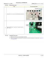
Page 644: ...2023 GE HealthCare GE HealthCare 9 Sunhwan ro 214 beon gil Jungwon gu Seongnam si Gyeonggi do 462 120 KOREA www gehealthcare com...

Reviews: