background image

LOGIQ C5/C5 PRO Quick Guide

Direction 5272220-100 Rev. 2

52

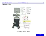
Console Labels 

(continued)

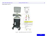
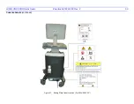
 Figure 29. Rating Plate Label Location (Korea only)

Summary of Contents for LOGIQ C5 Premium

Page 1: ...GE Healthcare Technical Publications Direction 5272220 100 Rev 2 LOGIQ C5 C5 PRO Quick Guide Copyright 2008 2009 By General Electric Co Operating Documentation...

Page 2: ...KG Beethovenstrabe 239 Postfach 11 05 60 D 42655 Solingen Germany Regulatory Requirement LOGIQ C5 C5 PRO complies with regulatory requirements of the following European Directive 93 42 EEC concerning...

Page 3: ...ER HISTORY Title Rev 2 1 Rev 2 1 52 Rev 2 Please verify that you are using the latest revision of this document Information pertaining to this document is maintained on MyWorkshop ePDM GE Healthcare e...

Page 4: ...h paitent screen 7 Mode Keys B Mode M Mode Pulsed Wave Doppler PW Modes and Color Flow CF Mode Press these key to activate the mode 8 Gain Auto Key Rotate the key to adjust the Gain Press the key to a...

Page 5: ...Function Keys Programmable Keys F1 Help Enter Online Help User Manual F2 Arrow Annotation Arrow F3 Eject Eject media F4 Spooler Activates DICOM Job Spooler screen F5 Activate Sub Menu F6 F12 Programm...

Page 6: ...Preview 6 Gray Color Bar 7 Cine Gauge 8 Measurement Summary Window 9 Image 10 Measurement not shown 11 Measurement Results Window 12 Probe Identifier Exam Study 13 Imaging Parameters by Mode current...

Page 7: ...t disconnect during system use If the system is accidentally unplugged data may be lost Press the Power On Off switch to turn the power on Figure 4 Power on Bottom a Power Switch Location LEDs 1 When...

Page 8: ...Disconnect the probes Clean or disinfect all probes as necessary Store them in their shipping cases to avoid damage Starting an Exam You need to select a pre configured dataflow that sets up the ultra...

Page 9: ...r to the actual exam being performed Details displays exam details and additional patient information EZBackup EZMove 3 One step method to backup move and delete patient images to an external media Da...

Page 10: ...le image colorization To deactivate reselect a Gray Map Gray Map Determines how the echo intensity levels received are presented as shades of gray Rotation Up Down Rotates the image by selecting the v...

Page 11: ...Dynamic Range Affects the amount of gray scale information displayed If you increase the gain you may want to decrease the dynamic range Edge Enhance Better delineates the amount of border crispness...

Page 12: ...ant map Packet Size Controls the number of samples gathered for a single color flow vector Controls in Common with B Mode For more information on Focal Zone Power Output Frequency Frame Average Dynami...

Page 13: ...LOGIQ C5 C5 PRO Quick Guide Direction 5272220 100 Rev 2 10 Color Flow Doppler Image Optimize continued Figure 11 CFM Top Sub Menu Controls Figure 12 PWD Top Sub Menu Controls...

Page 14: ...the ellipse and to size the measured axes move the calipers move the Trackball 7 To increase the size adjust the Ellipse control in a clockwise direction To decrease the size adjust the Ellipse contr...

Page 15: ...per with a vertical dotted line displays 2 To position the caliper at the desired measurement point move the Trackball 3 To complete the measurement press Set The system displays the velocity measurem...

Page 16: ...ally Swich the probe Swich probe between the two probe through pressing Probe bottom NOTE Swiching the probe frequently will cause probe can not be supported warning message Deactivating the probe Whe...

Page 17: ...ion E7C RC E6C RS 6 5C RS 4C RS 3 8C RC 7 5L RC 7L RC 3S RC Abdomen 0 X X 0 Small Parts X X X X Obstetrics X X X X Gynecology X X X Pediatrics X X X 0 0 Neonatal 0 0 0 Urology X X Cardiac X X X Endoca...

Page 18: ...Probes Probe Features Table 2 LOGIQ C5 C5 PRO Probe Features Probe Feature E7C RC E6C RS 6 5C RS 4C RS 3 8C RC 7 5L RC 7L RC 3S RC LOGIQ View X X X X X X X X Virtual Convex X X Virtual Apex X Easy 3D...

Page 19: ...em Probe Definitions Probe Designation Center Image Frequency MHz Doppler Frequency MHz Normal Penetration E7C RC 6 5 10 5 0 4 0 E6C RC 6 5 10 5 0 4 0 6 5C RC 6 5 10 5 0 4 0 4C RC 3 75 10 3 3 2 5 3 8C...

Page 20: ...ly marketed sterile pyrogen free probe sheath is REQUIRED Probes for neuro surgical use must not be sterilized with liquid chemical sterilants because of the possibility of neuro toxic residues remain...

Page 21: ...e manufacturer s recommended time Probes for neuro surgical intra operative use must NOT be sterilized with liquid chemical sterilants because of the possibility of neuro toxic residues remaining on t...

Page 22: ...ide of the screen Click Save As Select the Removable disk drive Select File Type DICOM JPG or AVI Provide File Name and press Save Before pulling out the memory stick the device should be stopped by c...

Page 23: ...ng button Figure 16 Connectivity Device Preset Menu Services better known as Destinations 1 Select the Server from the pull down menu 2 Press Add 3 Select all the services for this device from the pul...

Page 24: ...t and press Add Change its name to Jdicom Print For AE title enter Jdicom_Printer and for port number enter 7104 Figure 17 Connectivity Services Preset Menu Verify a Service Jdicom Image Storage Selec...

Page 25: ...for example 1 Name the Dataflow select from pull down menu or add a new dataflow 2 Configure the flow in the Dataflow section of the screen Select the service from the pull down menu and press Add Fig...

Page 26: ...Softkey to move to the beginning of the CINE Loop Adjust the Start Frame Softkey rightward to move forward through the CINE Loop Adjust the Softkey leftward to move backward through the CINE Loop Pres...

Page 27: ...interest is a tangible anatomical object that you can see and manipulate easily using the Trackball and Set control panel keys Practice positioning the pointer at different places within the 3D volume...

Page 28: ...ity tab select Service tab in Utility window netscape will show GEMS Service Home Page Select Operator in option of User Level enter correct password uls then press Okay Figure 22 Service Login Window...

Page 29: ...cifically Maintaining an optimum system environment Using this Manual Notes to emphasize or clarify a point DANGER Indicates that a specific hazard is known to exist which through inappropriate condit...

Page 30: ...7000 No 0659 Electrical Hazard Electrical micro shock to patient e g ventricular Probes ECG if applicable Connections to back panel Acoustic Output Hazard Patient injury or tissue damage from ultrasou...

Page 31: ...c information Equipment malfunction or incorrect settings can result in measurement errors or failure to detect details within the image The equipment user must become thoroughly familiar with the equ...

Page 32: ...ectrical Hazard A damaged probe can also increase the risk of electric shock if conductive solutions come in contact with internal live parts Inspect probes often for cracks or openings in the housing...

Page 33: ...l peripherals and accessories must be securely connected to the LOGIQ C5 C5 PRO DANGER The concerns listed below can seriously affect the safety of equipment and personnel during a diagnostic ultrasou...

Page 34: ...r possible Follow sterile procedures when appropriate Thoroughly clean probes and reusable accessories after each patient examination and disinfect or sterilize as needed Refer to Probes and Biopsy fo...

Page 35: ...by the enclosure per IEC60 529 IPX1 cannot be used in operating room environment IPX8 can be used in operating room environment Bottom of Foot Switch Type BF Applied Part man in the box symbol is in...

Page 36: ...ertain Hazardous Substances in Electronic Information Products The number in the symbol is the Environment friendly Use Period EFUP which indicates the period during which the toxic or hazardous subst...

Page 37: ...re is a pinch point on the LCD monitor Take care to avoid injuring hands of fingers when flipping down the LCD monitor On the back of LCD Use the rear handle for horizontal movement only On the back o...

Page 38: ...ly on BASIC INSULATION only but includes an protective earth ground This additional safety precaution prevents exposed metal parts from becoming LIVE in the event of an insulation failure 2 Class Il E...

Page 39: ...F APPLIED PART providing a degree of protection higher than that for Type BF Applied Part against electric shock particularly regarding allowable LEAKAGE CURRENTS Table 8 Type CF Equipment Normal Mode...

Page 40: ...ct the problem by one or more of the following measure s reorient or relocate the affected device s increase the separation between the equipment and the affected device power the equipment from a sou...

Page 41: ...uct In case of issues related to EMC please call your service personnel The manufacturer is not responsible for any interference caused by using other than recommended interconnect cables or by unauth...

Page 42: ...he ultrasound system or using an RF shielded examination room may be necessary 1 Use either power supply cords provided by GE Medical Systems or ones designated by GE Medical Systems Products equipped...

Page 43: ...oor EMC performance of the product 2 Notice against User Modification The user should never modify this product User modifications may cause degradation in EMC performance Modification of the product...

Page 44: ...he system conform to the requirements of IEC EN 60601 1 1 General precautions for installing an alternate device in patient environment would include 1 The added device must have appropriate safety st...

Page 45: ...Electromagnetic Environment CISPR 11 RF Emissions Group 1 Class A This system uses RF energy only for its internal function Therefore RF emissions are very low and are not likely to cause any interfe...

Page 46: ...be at levels characteristic of a typical location in a typical commercial and or hospital environment Separation distance to radio communication equipment must be maintained according to the method b...

Page 47: ...rinter Box 1 USB port Only for B W Printer 1 Front panel Probe Port Left side 1 USB port Peripheral devices B W Printer Officejet Printer Memory Stick Footswitch USB HDD ECG Color Printer Rear panel 2...

Page 48: ...s on page 41 for more information CAUTION Unapproved devices such as unsupported printers VCRs etc should not be used in the patient environment If devices are connected without the approval of GE the...

Page 49: ...perature increase in soft tissue Bone Thermal Index TIB Used when bone is near the focus of the image as in the third trimester OB examination it provides an estimate of potential temperature increase...

Page 50: ...ry and probe selected It takes effect when the system is powered on or New Patient is selected HINTS Increase the Acoustic Output only after attempting image optimization with controls that have no ef...

Page 51: ...published specifications Keep power to these devices turned off when near this equipment 3 The equipment weighs approximately 75 kg 165 lbs To avoid possible injury and equipment damage when transpor...

Page 52: ...LOGIQ C5 C5 PRO Quick Guide Direction 5272220 100 Rev 2 49 Safety Console Labels continued Figure 26 Rating Plate Label Location For 110V 120V AC...

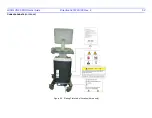
Page 53: ...LOGIQ C5 C5 PRO Quick Guide Direction 5272220 100 Rev 2 50 Console Labels continued Figure 27 Rating Plate Label Location For 220V 240V AC...

Page 54: ...LOGIQ C5 C5 PRO Quick Guide Direction 5272220 100 Rev 2 51 Safety Console Labels continued Figure 28 Rating Plate Label Location China only...

Page 55: ...LOGIQ C5 C5 PRO Quick Guide Direction 5272220 100 Rev 2 52 Console Labels continued Figure 29 Rating Plate Label Location Korea only...

Page 56: ...Mailing Address Fax To Fax Number Attention Coakley Tech 414 389 9130 Norm Keene Publication Language Direction Number Publication Language Direction Number Basic User Manual please select one languag...

Reviews: