GE M
EDICAL
S
YSTEMS
D
IRECTION
2380207
, R
EVISION
7
LOGIQ™ 5 PRO S
ERVICE
M
ANUAL
Chapter 8 Replacement Procedures
8 - 85
8-6-5
Bumper Set (FRU No. 405)
Purpose: This is a description on how to remove and replace the Bumper Set.
8-6-5-1
Tools
•
Common pillips screwdrivers
8-6-5-2
Needed Manpower
•
1persons, 20 m travel
8-6-5-3
Preparations
•
Shut Down the System and switch off the Main Breaker at the rear as described in section 4-3-2 on
8-6-5-4
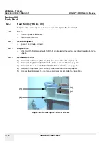
Removal Procedure
1.) Remove the Monitor Assy (FRU No.100). Refer to section 8-3-1 on page 2.
2.) Remove the Left Cover (FRU No.300). Refer to section 8-5-1 on page 41.
3.) Remove the Right Cover (FRU No.301). Refer to section 8-5-2 on page 43.
4.) Remove the Front Base Cover (FRU No.305). Refer to section 8-5-6 on page 51.
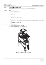
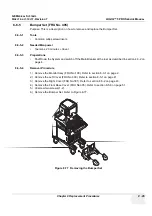
5.) Unscrew two screws (1-2).
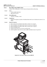
6.) Remove the Bumper Set. Refer to Figure 8-77.
Figure 8-77 Removing the Bumper Set
1
2
Summary of Contents for LOGIQ 5 PRO
Page 2: ...GE MEDICAL SYSTEMS DIRECTION 2407381 REVISION 7 LOGIQ 5 PRO SERVICE MANUAL Page 1 2 ...
Page 3: ......
Page 7: ...GE MEDICAL SYSTEMS DIRECTION 2380207 REVISION 7 LOGIQ 5 PRO SERVICE MANUAL ii iii ...
Page 462: ...GE MEDICAL SYSTEMS DIRECTION 2380207 REVISION 7 LOGIQ 5 PRO SERVICE MANUAL A 4 Index INDEX ...

