


– 23 –
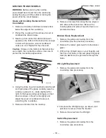
10-Pin
Header
10-Pin
Header
GEA00848
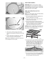
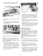
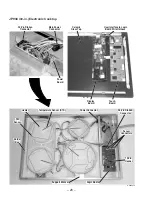
8. Prop the glass onto the back of the cooktop.
Using one hand to lower the glass, use the
other hand to connect the wire harness from the
user interface to the 10-pin header on the logic
board.
9. Lower the glass onto the burner box, being sure
not to pinch any wires between the frame and
the burner box.
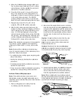
10. Apply power to the cooktop. An F161 is ac-
ceptable if a surface element is turned on with
the pan detection feature active. This indicates
the need to calibrate the inductive sensors.
11. Once the cooktop appears to be in working
order, remove power from the cooktop and
insert all the screws to secure the glass to the
burner box.
Note: After the cooktop has been placed back into
the consumer’s counter and power has been
applied, the cooktop
must be calibrated. Proceed
to the
Calibration Instructions for the Inductive
Sensors.
Press Down on Latching Tabs
Press Down on Latching Tabs
26-Pin
Ribbon Cable
26-Pin
Ribbon Cable
GEA00823
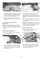
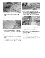
3. Disconnect the 26-pin ribbon cable from the
logic board by pressing down on the latching
tabs of the header.
Tabs
Tabs
GEA00824
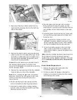
4. Remove the logic board by using needle nose
pliers to press in on the tabs of the logic board
standoffs, and lifting the board. Do
not remove
the logic board standoffs. Repeat this proce-
dure for all 5 board standoffs.
Caution: To avoid delivering an electric shock to
the new logic board, place your hand on the
burner box for
at least 2 seconds before reaching
for the new logic board.
5. Remove the new logic board from the antistatic
bag and place it on top of the standoffs.
Note: 30-in. cooktops do not have a connector
placed on J503 (for the CR heater of a 36" unit),
and the connectors are keyed to prevent a
misconnection.
6. Reconnect the 26-pin wire harness and the
sensor connectors to their original positions.
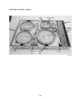
7. Examine the inside of the cooktop (heaters,
sensors, wires, and thermal wall) for anything
that does not look normal.
Power Board Replacement
1. Remove the glass and cooktop from the
countertop (see procedure).
2. Turn the cooktop 180 degrees and prop the
cooktop up to access the drop box. Be careful
not to damage the counter.
Summary of Contents for JP350
Page 19: ... 17 Fault Code Behavior Table ...
Page 33: ... 31 Notes ...
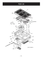
Page 34: ... 32 Parts List ...
Page 36: ... 34 ...
Page 38: ......
Page 39: ......