background image

– 39 –

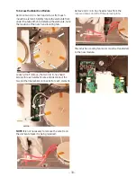
2.  To access the LED power supply or Sync Burner 

relays, remove 1/4 in. hex head screws from the 
cover. 

  Radiant Element Access

1.  Disconnect the two wire connector to the buzzer. 

,Q¿QLWH6ZLWFK&RPSRQHQW$FFHVV

1.  Remove power to the cooktop. 

2.  Carefully remove the cooktop from the 

installation and lay glass side down on 
protected surface. 

127(5HPRYHWKHNQREVLIDFFHVVWRWKHLQ¿QLWH

heat switches is necessary and use caution as the 
weight of the cooktop will be resting on the switch 
shafts.

7R$FFHVVWKH:LULQJRIWKH,Q¿QLWH6ZLWFKHV

1.  Remove the four 1/4 in. hex head screws from 

the cover.

Summary of Contents for JP3030*J series

Page 1: ...ops Technical Service Guide November 2015 GE Appliances 36 Radiant Cooktops JP3536_J JP5036_J PP7036_J PP9036_J CP9536_J ZEU36R_J 30 Radiant Cooktops JP3030_J JP3530_J JP5030_J PP7030_J PP9030_J CP953...

Page 2: ...G To avoid personal injury disconnect power before servicing this product If electrical power is required for diagnosis or test purposes disconnect the power immediately after performing the necessary...

Page 3: ...ng Electronic Control Cooktop Elements 16 Service Mode for Electronic Control Cooktop 18 Induction Cooktop Features 21 Normal Operating Sounds 23 PHP Model Features 24 ZHU Model Features 25 30 Inducti...

Page 4: ...oes for all repairs Steel Toed Work Boot Electrically Rated Glove and Dyneema Cut Resistant Glove Keeper Dyneema Cut Resistant Glove Plano Type Safety Glasses Prescription Safety Glasses Safety Glasse...

Page 5: ...ng The Precision Cooking Probe communicates with the control board via the Bluetooth module to maintain proper temperature for Sous Vide cooling French for under vacuum Sous vide is a method of cookin...

Page 6: ...types of keypads The Slew control has and pads with a single digit display for each element The Horseshoe control has and pads with a sweeping display for each element Introduction continued Slew Cont...

Page 7: ...t M 27 Drop in N Hood non vented P Cooktop S Slide in R Wall Oven 24 Cabinet T Wall Oven 30 Cabinet V Hood vented X Accessory Feature Package Designates features The higher the number the more feature...

Page 8: ...lement 8 5 Dual 2200 watt element Sync Burners Controls two 7 elements simultaneously to evenly heat large cookware or griddle Multi element Timer Individual timer for each element Control Lock capabi...

Page 9: ...ccess 1 Disconnect power to the cooktop 2 Carefully remove the cooktop from the installation and lay the glass side down on a protected surface To Access the Power Supply Board 1 Remove four 1 4 in he...

Page 10: ...ove six 1 4 in hex head screws and separate the board from the cooktop 3 The display board has a small connector that mates with the board mounted to the glass The board can be removed without removin...

Page 11: ...11 To Access the Relay Board 1 5HPRYH YH LQ KH KHDG VFUHZV IURP WKH UHOD ERDUG FRYHU Relay Board...

Page 12: ...12 Wiring Diagram Electronic Control...

Page 13: ...13 Schematic Electronic Control...

Page 14: ...ay the glass side down on a protected surface 3 5HPRYH YH LQ KH KHDG VFUHZV IURP WKH UHOD ERDUG FRYHU 4 Check the resistance from J501 pin 1 grey black to J501 pin 3 grey It should measure approximate...

Page 15: ...dicators get a signal from the main control board On these models if the touch board needs to be replaced the glass cooktop must be replaced The touch board and glass cooktop are a single assembly The...

Page 16: ...rom the power supply board and one from the RJ45 connector Set the assembly aside 6 5HPRYH YH LQ KH KHDG VFUHZV IURP WKH relay board cover 7 Disconnect the three multi pin connectors and both sets of...

Page 17: ...17 13 Large elements also have a bracket that secures with one 1 4 in screw...

Page 18: ...ashes appear showing the end of the codes If no active faults exist only dashes will be shown with each press OO 2 Pressing and holding for 5 seconds will clear the Fault Code that is currently displa...

Page 19: ...ace Display Board under Touch Board F7x User Interface UI Button Matrix Error Replace Touch Board F82 User Interface UI Microprocessor Error Replace Display Board under Touch Board Machine Control MC...

Page 20: ...e Timer Select or Time Start on models where this key is available for 7 seconds to store the model code in the control 5 The control will restart and operate normally Model Code Description CHP9530xx...

Page 21: ...ement Slide touch controls Sync Burners Controls two 7 elements simultaneously to evenly heat large cookware or griddle Stainless Steel Clad Aluminum Griddle LJKWZHLJKW JULGGOH WDLORUHG WR W Sync Burn...

Page 22: ...contents of the pan are therefore heated more TXLFNO WKDQ WKH ZRXOG EH LI KHDWHG E D JDV DPH or a traditional radiant heating element By heating only the bottom of the pan the surrounding surface rema...

Page 23: ...w whistle or intermittent hum These noises can be reduced or eliminated by lowering or raising the power level settings of one or both of the elements Pans that completely cover the element ring will...

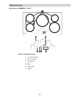
Page 24: ...PHP Model Features User Interface Controls 30 wide cooktop 2 3 6 4 8 7 5 1 1 Cooking Element s 2 OHPHQW 2Q 2 3 Sync Burners 4 OO 2 5 Lock 6 7LPHU 2Q 2 7 Display 8 Start Timer User Interface SLEW Cont...

Page 25: ...25 ZHU Model Features 2 3 7 4 6 5 1 ZHU36 36 Induction Cooktop 1 Cooking Element s 2 Power Level Arc 3 Sync Burners 4 OO 2 5 Lock 6 Timer Select 7 Display User Interface HORSESHOE Control...

Page 26: ...itchen Timer To Turn On Touch the Timer Select pad Touch the up or down v arrows to choose the desired number of minutes The timer automatically starts 3 seconds after pad is touched The ON LED will a...

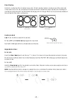
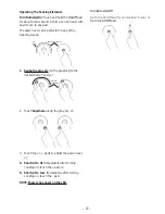
Page 27: ...the graphics to the desired power level or 2 Touch Anywhere along the gray arc or 3 Touch the or pads to adjust the power level or 4 Shortcut to Hi Immediately after turning cooktop on touch the pad o...

Page 28: ...gs C01 Factory Reset Clears customized settings and restores defaults C02 Custom settings activated Not visible unless any other custom setting is selected Automatically on when any other custom setti...

Page 29: ...cooking Never place or store any items on the griddle even when it is not in use The griddle can become heated when using the surrounding surface cooktops Avoid using metal utensils with sharp points...

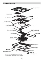
Page 30: ...le Bracket Hold Down 2x Gasket Bottom Control assembly with boards Housing RJ45 Board RJ45 Connector Board Filter Gasket Fan Blower Centrifugal 12V Insulation Induction Element Induction 4X Board ASM...

Page 31: ...n Element Induction 5X Board ASM Display Blower Centrifugal 12V Right Blower Centrifugal 12V Left Board Generator ASM Right Board Generator ASM 2X Left Gasket Fan Left Board Filter Right Board Filter...

Page 32: ...Remove T20 screws from the perimeter 4 Raise the bottom cover about six inches and disconnect the two L1 L2 and ground wires from the module 5 Disconnect the RJ45 harness connector 6 Remove the botto...

Page 33: ...in hex head screws from each induction element Slightly rotate the elements from under the tabs When reinstalling the elements note the location of the notch and locating tab Loosen don t remove the t...

Page 34: ...ith the Display board on PHP or JP models the processor is part of the board mounted to the glass cooktop and the cooktop will have to be replaced Hot surface indicators are part of the display board...

Page 35: ...ess and hold the Timer Select or Timer Start on models where this key is available for 7 seconds to store this model number in the control 5 The control should restart and operate normally MODEL SELEC...

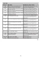
Page 36: ...necting UI to Induction Tray Check Fan UI and induction Tray Replace fan FA1 Fan1 is not running at the correct Low speed Check wires connecting UI to Induction Tray Check Fan UI and induction Tray Re...

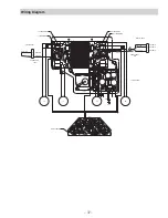
Page 37: ...4 BOARD ID BOARD ID 2 00 1BK 2BK GEN BOARD LT J502 229C6361G001 DISPLAY BOARD 1 2 3 4 BOARD ID BOARD ID 1 25 1BK 1 25 2BK GEN BOARD RT J502 C7 4BK 1 25 3BK BOARD ID 229C6361G002 RR THERMISTOR RF THER...

Page 38: ...imultaneously to evenly heat large cookware or griddle Stainless Steel Clad Aluminum Griddle LJKWZHLJKW JULGGOH WDLORUHG WR W Sync Burners Keep Warm Setting Keeps food warm with GE s lowest heat setti...

Page 39: ...SRQHQW FFHVV 1 Remove power to the cooktop 2 Carefully remove the cooktop from the installation and lay glass side down on protected surface 127 5HPRYH WKH NQREV LI DFFHVV WR WKH LQ QLWH heat switches...

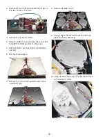
Page 40: ...one 1 4 in screw 2 Disconnect two multi pin connectors and two L1 and two L2 wire connectors 3 Remove the perimeter screws 4 Raise the bottom cover and slide the connectors through the rubber grommet...

Page 41: ...et to access the display and the neon indicators NOTE Grommets shown below are pushed through the glass cooktop On parts look up the grommets are shown between the bracket and display 3 The LED Boards...

Page 42: ...42 Q QLWH 6ZLWFK 6FKHPDWLF...

Page 43: ...43 Q QLWH 6ZLWFK Wiring Diagram...

Page 44: ...44 Accessories Parts Griddle JXGRIDL1 Sous Vide Kit JXSOUSV1 Stainless Steel Cleaner and Polisher PM10X311...

Page 45: ...20 33 Infinite Switch Component Access 38 Infinite Switch Schematic 41 Infinite Switch Wiring Diagram 42 K Kitchen Timer 25 L LED Display 40 M Model Code 19 34 N Noise 22 P Power Sharing 25 Power Sup...

Page 46: ...rranty GE will also provide free of charge all labor and in home service to replace the defective part Servicing your appliance may require the use of the onboard data port for diagnostics This gives...

Reviews: