WHEN ALL HOOKUPS ARE
COMPLETED
Make sure all controls are left in the off
position. Make sure the flow of combustion and
ventilation air to the range is unobstructed.
Check that all packing materials and tape
have been removed. This will include tape on
metal panel under control knobs (if applicable),
adhesive tape, wire ties, cardboard and
protective plastic. Failure to remove these
materials could result in damage to the
appliance once the appliance has been turned
on and surfaces have heated.
7
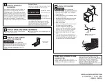
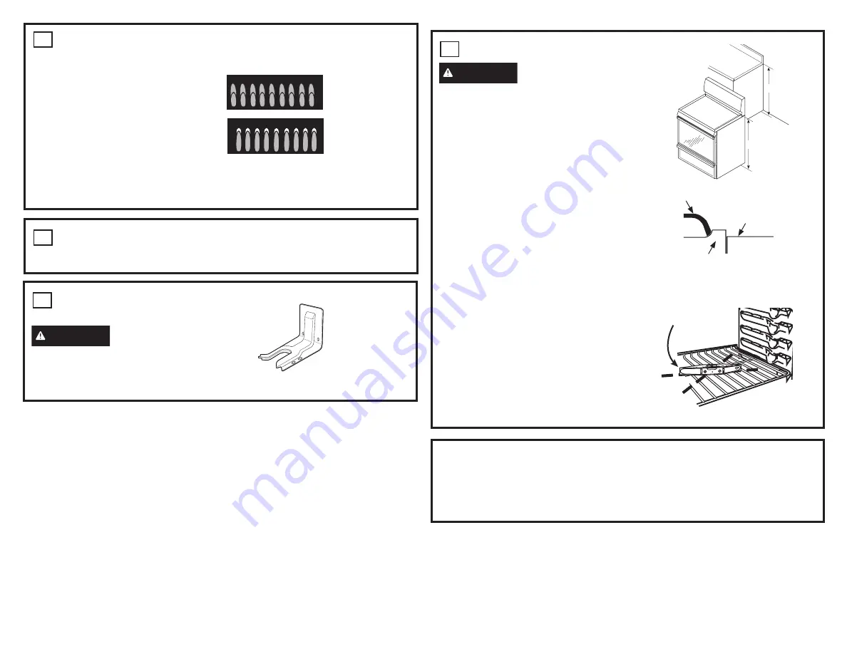
LEVEL THE RANGE
WARNING
Never completely
remove the leveling leg as the range will not
be secured to the anti-tip device properly.
A.
Plug in the unit.
B.
Measure the height of your countertop at the
rear of the opening (X).
C.
Adjust two rear leveling legs so that the rear
of cooktop is at the same height or higher
than the counter (Y).
D.
Slide unit into place.
E.
Install oven shelves in the oven and position
the range where it will be installed.
F.
Check for levelness by placing a spirit
level on one of the oven shelves. Take two
readings—with the level placed diagonally
first in one direction and then the other.
G.
Adjust front leveling legs until the range is
level.
H.
Look under the unit and verify that the rear
leg is fully engaged with the anti-tip device. If
not, remove the unit and adjust the height of
the rear leg so that it is properly engaged.
Spirit level
X
Y
NOTE:
Cooktop must be
at or above counter.
Grate
Cooktop
Counter
6
INSTALL AND CHECK
ANTI-TIP DEVICE
WARNING
Never completely
remove the leveling leg as the range will not
be secured to the anti-tip device properly.
Follow instructions supplied with ANTI-TIP
bracket
Anti-Tip Bracket
Kit Included
5
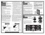
CHECK BAKE AND BROIL BURNERS
Set Bake function to 350°F. Burner should
light in 30 to 60 seconds.
Set broil to Broil Hi. Burner should light in 30
to 60 seconds
4
CHECK SURFACE
BURNERS
Push and turn a knob to the LITE position. A
clicking sound indicates proper operation of
the ignition system. When lighting any burner,
sparks will appear at all burners but gas flows
from only the one selected. Once air is purged
from the supply line, burner should light within
4 seconds. After burner lights, rotate the knob
out of the LITE position. Try each burner in
succession until all burners have been checked.
Quality of Flames
Determine the quality of flames visually. Normal
burner flames should look like (A) or (B).
Long, bright yellow flames are not normal.
Normal flames may show signs of an orange
tint when well heated or signs of flickering
orange due to particles in the gas or air.
(A) Soft blue flames—
Normal for natural gas
(B) Yellow tips on
outer cones—
Normal for propane gas
INSTALLATION INSTRUCTION
31-11005 Rev. 1 01-20 GEA
JGB860, JGBS86


