


••••
Auxiliary Drive to ISBus Interface Board IS200ADII
GEI-100305
14
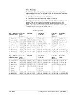
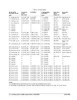
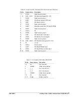
Table 14. P2 Connector, RJ45 ISBus TX/OUT
Pin No.
Nomenclature
Description
1, 2
NC
Not connected
3
ISBTXP
ISBus transmit positive
4, 5
NC
Not connected
6
ISBTXN
ISBus transmit negative
7, 8
NC
Not connected
9, 10
Shield
Shield connection
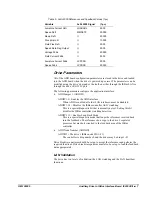
Installation and Renewal/Warranty Replacement
How to Order a Board
When ordering a replacement board for a GE drive, you need to know:
•
How to accurately identify the part
•
If the part is under warranty
•
How to place the order
This information helps ensure that GE can process the order accurately and as soon
as possible.
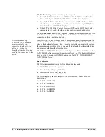
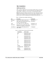
Board Identification
A printed wiring board is identified by an alphanumeric
part (catalog) number
located near its edge. Figure 3 explains the structure of the part number.
The board’s functional acronym, shown in Figure 3, is normally based on the
board
description
, or name. For example, the ADII board is described as the Auxiliary
Drive to ISBus Interface board.
IS 200 ADII H# A A A
1
Backward compatible
2
Not backward compatible
3
200
indicates a base-level board;
215
indicates a
higher-level assembly or added components (such
as PROM)
Manufacturer (
DS
&
IS
for GE in Salem, VA)
Assembly level
3
Functional acronym
Group (variation, G or H)
Functional revision
2
Functional revision
1
Artwork revision
1
Figure 3. Board Part Number Conventions


