Chapter 2
.
Getting Started
12
Qui User’s Manual–November 2013
GFK-2847
A 24VDC power supply. For requirements, see the Input power specification on page
8.
A power terminal block is supplied.
Power cord
with
30
– 14 AWG (0.05 – 2.00 mm
2
) wires
USB-compatible keyboard (optional)
USB-compatible mouse (optional)
2.3.1
Connecting Input Power
1. Make sure that the power cable is not energized
and that the Qui unit is not on.
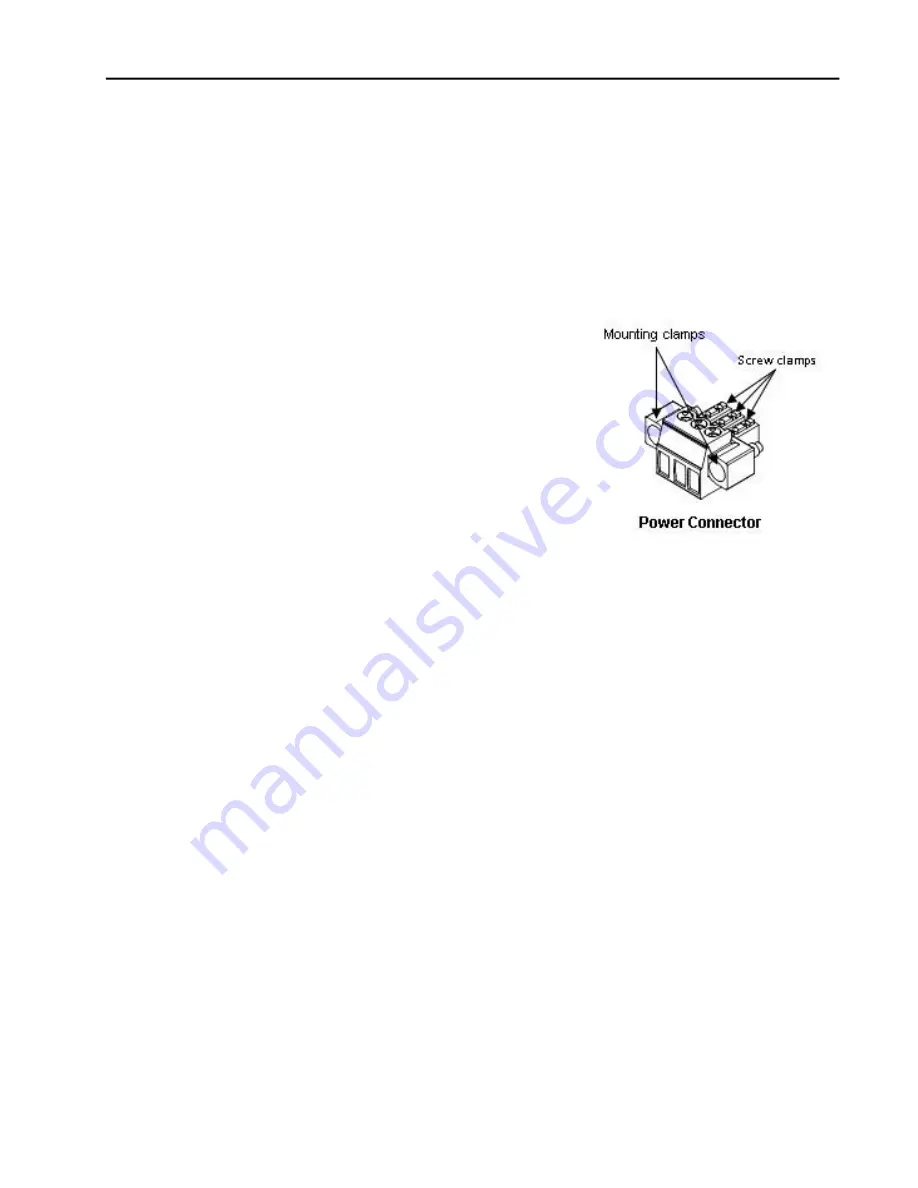
2. Loosen the screw clamps on the mating power
connector
3. Strip the insulation from the power cables.
4. Secure the power cable to the mating connector
while noting polarity and tighten the screw clamps.
The torque for the attaching screws is 0.31 Nm.
5. Apply DC power to the unit.
During normal power up and operation, the
QuickPanel Status LED display is:
Solid amber
while the Qui unit is starting up
Solid green
during normal operation
6. Once power is applied, the Qui begins initializing. The first thing to appear on the
display is the splash screen.
To skip running any programs included in the StartUp folder, tap
Don’t run StartUp
programs
.
7. The Microsoft Windows Embedded Compact 7 operating system starts automatically.
During powerup, you should see the normal operating system starting displays.
To activate the operating system online, you will need to first configure the Ethernet
settings for operation on your network, as described in “Initial Configuration.”
You can find the operating system product key on the Microsoft Certificate of Authenticity
label, which is on the back of the Qui.
Summary of Contents for IC754CSL12CTD
Page 5: ......
Page 22: ...Chapter 4 Installation 22 QuickPanel User s Manual November 2013 GFK 2847 ...
Page 35: ......


