GEk-86105
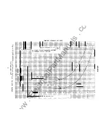
TABLE X
T
ar
g
e
t
/
Cu
rre
nt
Current
Current
Se
a
l
-in
Connection
0. 2
2.0
0.2
2. 0
Induction &
Standard
0.12-. 195
1.2-1. 95
0. 06+
0.6
+
I
ns
tanta
n
eous
Close Induction
Circuit
Unit Contact
Hi-0. 0. Inst.
Studs 8-10
& ox
0. 12-.195
1.2-1.
95
0. 06+
0.6 +
Telephone Relay Close Hi-0. 0.
C
i
r
cu
i
t
& OX Tel . Relay
Instantaneous Units
There are two instantaneous units in the lAC 66M relay. The standard instantaneous
unit is located in the lower right side of the relay, with electrical connections on
studs
4
a
n
d 7.
Pickup is obtained with the adjustable core, which is adjustable for
the complete pickup range of the unit (see page 8-9).
It should be possible to
attain the minimum pickup value without turning the core to its absolute minimum
position.
The other instantaneous unit is a high-dropout unit, similar to the standard unit
except that it should drop out at 80% of p
i
c
k
u
p
or higher when the
current is
g radu
a
lly reduced. The electrical connections are
on
studs 6 and
7 for
this unit.
INSTALLATION
MOUNTING AND CONNECTIONS
Outline and panel drilling dimensions are shown in Figure
3.
Unless the re
l
ay
is
mounted on a steel panel which adequately grounds the relay case, the case should be
grounded through a mounting stud o
r screw
with a conductor not less than No. 12 B&S
gag
e
copper wire, or equivalent.
Internal connections are shown in
F
igur
e
9A;
Figure 9B s
h
o
w
s the internal
connections for forms 51 and up.
Use a
test source of
120 volts or greater with
good
wave form and constant
frequency
when
making settings on the induction unit.
Step-down transformers or "phantom
loads" should not be used in testing induction units, since they may cause a
distorted
wave form.
A
setti
n
g that can be obtained by one of the tap positions
will
be
satisfactory, and no
further
a
d
j
us
t
m
e
n
t will be
required.
H
o
we
v
er
,
sometimes a pickup s
e
tting
might
fall between available tap positions.
Such
intermediate
settings
can be
ob
t
a
ined by placing
the
tap screw in the tap position
nearest the required pickup, and adjusting the control spring until the required
pickup
is
obtained.
Refer
to
SERVICING
for
a more detailed descr
i
p
t
i
o
n
of
pickup
adjustment.
13
www
. ElectricalPartManuals
. com


