GE M
EDICAL
S
YSTEMS
D
IRECTION
2317229, R
EVISION
3
LOGIQ™ 180 B
ASIC
S
ERVICE
M
ANUAL
3 - 24
Section 3-6 - System Configuration
B.) Footswitch Connection
The foots witch which is the remote
FREEZE
device is connected to the rear panel of the system. this
extra
FREEZE
switch is provided to enhance flexibility to freeze images when the system is not within
reach of the user.
Pin Assignment of Foot Switch Connector
C.) Video Graphic Printer (VGP)
Connect the Video Graphic printer (with BNC to BNC cable) Video IN to the Video OUT located on the
rear panel of the system, also establish shutter (with Mini Jack cable) if required.
Model: (Sony UP-890MD/CE/MDG or UP-895MDW/MD/SYN) / (Mitsubishi P91E)
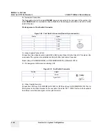
D.) Pin Assignment of Mini Jack controlling VGP
E.) Video Casette Recorder
Connect the VCR Sony SVO-9500MD (H4120SR) for NTSC and Sony SVO 9500MDP(E11801AA) for
PAL System to the Video IN socket in the rear panel. Press the “EXT. VIDEO” button on the keyboard
to enable an external video signal on the system monitor.
Figure 3-24 Foot Switch Connector (Round 5-pin connector)
Pin No.
Signal
1
Foot Switch
2
GND
3
GND
4
GND
5
GND
Figure 3-25 Foot Switch Connector
Pin No.
Signal
1
Shutter
2
Signal GND

