background image


3.3.6 

Standard installation procedure 


NOTE 

Ensure that the UPS is isolated prior to installation;

 no live input source may be connected 

to the UPS during the installation procedure. Open all the input/output switches/breakers on 

the power distribution and ensure no one is able to close them during this installation step.


1. 

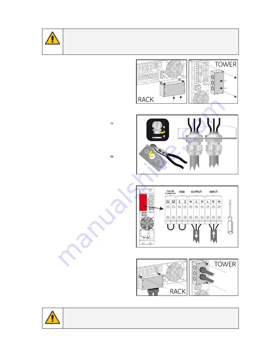
Remove the terminal cover (fig. 3.3.6.a).


2.  Punch out the appropriate holes in the 

terminal cover. Secure the input/output 

cables using glands, according to 


fig. 3.3.6.b.


3.  Input. Connect the mains supply wires to 

the terminals “L” (Line) and “N” (Neutral) and 
the ground wire to terminal “ ”. 

Ground 

connection is essential! 

(fig. 3.3.6.c).


4.  Output. Connect the load wires to the 

terminals “L” (Line) and “N” (Neutral) and 
the ground wire to terminal “ ”. 

Ground 

connection is essential! 

(fig. 3.3.6.c).


5. 

Re-install

 the terminal cover (fig. 3.3.6.d). 


6.  Ensure the battery cable is connected 

between the battery cabinet and the 

power unit. (see 3.3.3). 


7. 

Connect the utility power to the UPS. 


8.  For a quick start proceed with section 

4.2.1.


If parallel-operating units will be installed, please 

proceed with section 3.4. Otherwise, proceed with 

section 4.


fig. 3.3.6.a 


fig. 3.3.6.b


fig. 3.3.6.c


fig. 3.3.6.d


NOTE 

The UPS output sockets are live soon as the UPS is connected to the mains, even if the UPS 

has not been switched on via the front panel.


modifications reserved


11


User manual GT Series 6 - 10 kVA UPS 1.0 (GB)


www.upsdirect.com 

   08456 

445 

002

Summary of Contents for GT6000

Page 1: ...GE Digital Energy Power Quality User manual Digital Energy Uninterruptible Power Supply GT Series UPS 6 10 kVA imagination at work w w w u p s d i r e c t c o m 0 8 4 5 6 4 4 5 0 0 2...

Page 2: ...el GT Series 6 10 kVA Series 1 Date of issue 15 06 2008 File name OPM_GTS_XCE_6K0_10K_XGB_V010 Revision 1 0 Identification No Up dating Revision Concern Date General Electric Consumer Industrial SA Al...

Page 3: ...a parallel system 15 4 3 Use normal operation 15 4 3 1 Normal operation conditions 15 4 3 2 Switching off 15 4 4 Use status and alarm indications 16 4 4 1 On bypass 17 4 4 2 On battery 17 4 4 3 Batte...

Page 4: ...ome of the information contained in this manual may be changed without notice 1 2 SAFETY RULES CAUTION RISK OF ELECTRIC SHOCK The UPS contains batteries The appliance outlets may be electrically live...

Page 5: ...Never try to lift the unit by yourself No liability can be accepted for any transport damage when the equipment is shipped in non original packaging Store the UPS in a dry location with the batteries...

Page 6: ...is 220 240 Volts and 50 Hz if the mains frequency is 60Hz the output frequency of the UPS can be changed see note in section 4 4 4 and The total power demand of the connected equipment does not exceed...

Page 7: ...2 fig 3 3 1 3 Mount the front panel by pushing the plastic part into the appropriate holes 3 fig 3 3 1 4 Install the UPS into a 19 rack The UPS cabinet must be supported by mounting rails do not moun...

Page 8: ...o the UPS cabinet 4 fig 3 3 2 b 5 Mount the front panel on the UPS and on battery cabinet 5 fig 3 3 2 b c 6 Attach the display sticker to the battery cabinet 4 fig 3 3 2 c The GT Series UPS is now rea...

Page 9: ...UPS is connected to the mains and the battery pack is connected to the UPS the batteries start charging For best results allow the UPS to recharge the batteries during a period of approx 8 hours It is...

Page 10: ...or 5 Parallel port 6 DB9 communication port 7 RPO contacts see 4 4 11 8 SNMP card slot 9 Fan 10 Input circuit breaker 2 pole 30A 250Vac 6kVA 2 pole 63A 250Vac 10kVA 11 Output sockets IEC320 16A 12 Out...

Page 11: ...essential fig 3 3 6 c 4 Output Connect the load wires to the terminals L Line and N Neutral and the ground wire to terminal Ground connection is essential fig 3 3 6 c 5 Re install the terminal cover...

Page 12: ...tput wiring in order to be able to isolate a unit from the remaining system for service and maintenance purposes 3 The diameter of input and output cables must be according to the table in the install...

Page 13: ...om parallel connection terminals on the power unit terminal block fig 3 4 2 a 3 The parallel cable connection slot is at the rear of the power unit Remove terminal cover fig 3 4 2 b 4 Connect the cabl...

Page 14: ...input voltage is out of bypass tolerance see section 4 4 4 for more details 7 LED alarm red on in case of alarm 8 LED bar runtime capacity the remaining available battery runtime for the actual load...

Page 15: ...ared between the UPS as shown on the LED bar load 4 3 USE NORMAL OPERATION 4 3 1 Normal operation conditions 1 The mains supply is present or within the tolerance see chapter 9 2 The UPS is on 3 The l...

Page 16: ...5 5 1 0 5 sec Battery not connected 4 5 0 4 Replace battery 4 4 5 1 3 0 4 1 60 sec Bypass out of limits 4 4 4 1 5 0 4 o On bypass 4 4 1 1 5 0 4 1 120 sec o On battery 4 4 2 1 5 0 4 Battery low 4 4 3...

Page 17: ...ly part of the output capacity of the UPS is used this period can be longer with aged batteries this period can be shorter When the batteries are fully discharged the UPS is no longer able to supply t...

Page 18: ...l Alarm 1 60 secs Battery test failed see section 4 5 1 120 secs On bypass see section 4 4 1 4 4 8 Fault mode The UPS may be in fault mode if the following failure occurred Indicators on Battery Charg...

Page 19: ...he unit fig 4 4 11 4 4 12 No load shutdown If this function is enabled and the load is 5 the UPS will in case of a mains failure switch off and output power is lost No load shutdown is disabled as def...

Page 20: ...ions see section 4 3 1 In case of failure the corresponding alarm will be generated see section 4 4 6 4 4 7 Deep battery test A deep battery test will update the runtime calculation and may be started...

Page 21: ...MP INTERFACE CARD OPTION This card allows the data interface to be connected directly to an Ethernet network The card is fitted into the SNMP Card slot 8 fig 3 3 5 a For more information please refer...

Page 22: ...sing materials and components respecting eco design rules It does not contain CFCs Carbon Fluorine Chloride of HCFCs Halogen Carbon Fluorine Chloride The batteries contain lead which is a harmful subs...

Page 23: ...me type and size Never short the battery terminals Shorting may cause the battery to burn When working with batteries remove watches rings or other metal objects and only use insulated tools Avoid cha...

Page 24: ...No mains voltage present Read section 4 4 2 UPS on battery Mains indicator not illuminating mains voltage present acoustic alarm intermittent Input fuse blown or circuit breaker tripped Replace fuse o...

Page 25: ...overload and short circuits Overload behaviour during battery operation 125 during 1 minute 150 during 10 seconds Overload behaviour during bypass operation depends on rating of thermal circuit breake...

Reviews: