GE GN75DNSRSA Installation Instructions Manual Download Page 2

Installation Instructions

2

SAFETY PRECAUTIONS (cont.)

WARNING:

Do not use substitute

materials. Use only parts certified with the
appliance.

• This appliance must be installed, inspected and

leak tested by a state- or city-qualified licensed
contractor. It is the responsibility of the person
having the water heater installed to ensure the
installing contractor has proper licenses and
permits for installing water heaters in your
location. GE highly recommends that installers
attend a product knowledge class to ensure
customer satisfaction and warranty coverage.
Failure to comply with state and local codes
pertaining to water heater installations may
void the warranty.

• This appliance is not to be installed outdoors.

• The installation must conform with local codes or,

in the absence of local codes, with the

National

Fuel Gas Code, ANSI Z223.1/NFPA 54

, or the

Natural Gas and Propane Installation Code,
CSA B149.1

.

• The appliance and its appliance main gas valve

must be disconnected from the gas supply piping
system during any pressure testing of that
system at test pressures in excess of 1/2 psi
(3.5 kPa) (13.84 in W.C.).

• The appliance must be isolated from the gas

supply piping system by closing its individual
manual shut-off valve during any pressure
testing of the gas supply piping system at test
pressures equal to or less than 1/2 psi (3.5 kPa)
(13.84 in W.C.).

• Carefully follow the venting instructions

beginning on page 19 and in the

Maintenance

section in the Owner’s Manual for adequate
combustion and ventilation air.

• The appliance should be located in an area

where water leakage of the unit or connections
will not result in damage to the area adjacent to
the appliance or to lower floors of the structure.
When such locations cannot be avoided, it
is recommended that a suitable drain pan,
adequately drained, be installed under the
appliance. The pan must not restrict combustion
airflow.

SAFETY PRECAUTIONS (cont.)

• The flow of combustion and ventilation air shall

not be obstructed.

• This appliance is not suitable for use in an

application such as a pool or spa heater that
uses chemically treated water. (This appliance
is suitable for filling large or whirlpool bath tubs
with potable water.)

• If a water heater is installed in a closed-water

supply system, such as one having a backflow
preventer in the cold water supply line, means
shall be provided to control thermal expansion.
Contact the water supplier or local plumbing
inspector on how to control this situation.

• Should overheating occur or the gas supply fail

to shut off, turn off the manual gas control valve
to the appliance.

• Keep the air intake (at the flue terminal external

to the home) location free of chemicals, such as
chlorine or bleach, that produce fumes. These
fumes can damage components and reduce
the life of your appliance.

CAUTION:

DO NOT operate the water

heater if any part of the appliance has been under
water.

CAUTION:

BURN HAZARD.

Hot exhaust

and vent may cause serious burns. Keep back from
water heater unit. Keep small children and animals
away from unit.

CAUTION:

Hot Water outlet pipes leaving

unit can be hot to touch. Insulation must be used
for hot water pipes below 36

due to burn risk to

children.

WARNING:

This unit is not intended

or qualified for use in manufactured homes, mobile
homes or recreational vehicles.

DANGER

Read and follow water heater warnings and
instructions. If owner’s manual is missing, contact
the retailer or manufacturer.

Summary of Contents for GN75DNSRSA

Page 1: ...r damages caused thereby SAFETY PRECAUTIONS WARNING If the information in these instructions is not followed exactly a fire or explosion may result causing property damage personal injury or death FOR YOUR SAFETY Do not store or use gasoline or other flammable vapors or liquids or other combustible materials in the vicinity of this or any other appliance To do so may result in an explosion or fire...

Page 2: ...s will not result in damage to the area adjacent to the appliance or to lower floors of the structure When such locations cannot be avoided it is recommended that a suitable drain pan adequately drained be installed under the appliance The pan must not restrict combustion airflow SAFETY PRECAUTIONS cont The flow of combustion and ventilation air shall not be obstructed This appliance is not suitab...

Page 3: ...trical Box Wire Nuts Concrete Wall Anchors Optional Your installation components may vary PARTS PROVIDED Locate the parts packed with the Water Heater Gas Valve 3 4 FNPT Ball Valve 4 10 x 11 4 Wood Screws OTHER TOOLS THAT MIGHT BE REQUIRED Hammer Drill with Concrete Bits Saw Threading Machine with Heads and Oiler Core Drill with Diamond Head Torch Set Copper Tubing Cutter Steel Pipe Cutter OTHER M...

Page 4: ...5 8 244 5 C Height Unit 227 8 582 D Height with brackets 251 2 647 7 E Hot Water Outlet from wall 35 8 91 F Hot Water Outlet from center 45 16 110 G Cold Water Inlet from wall 213 16 70 H Cold Water Inlet from center 11 8 27 I Gas Connection from wall 37 8 99 J Gas Connection from center 31 2 89 From base to gas connection 15 8 40 K From base to cold connection 2 50 From base to hot connection 15 ...

Page 5: ...or sags in horizontal vent runs by installing supports per the vent manufacturer s instructions Support horizontal vent runs every four feet and all vertical vent runs every six feet or in accordance with local codes Venting should be as direct as possible with a minimum number of pipe fittings Vent diameter must not be reduced Do not connect the venting system with an existing vent or chimney Do ...

Page 6: ...sembly I Clearance to service regulator vent outlet J Clearance to nonmechanical air supply inlet to building or 12 inches 30 cm the combustion air inlet to any other appliance K Clearance to a mechanical air supply inlet 3 feet 91 cm above if within 10 feet 3 m horizontally L Clearance above paved sidewalk or paved driveway located on public property1 M Clearance under veranda porch deck or balco...

Page 7: ...RMINAL These clearances are applicable to both concentric terminations and nonconcentric vent exhaust terminations Local codes supersede these clearances Avoid termination locations near a dryer vent Avoid termination locations near commercial cooking exhaust ...

Page 8: ...Installation Instructions 8 FLUE INSTALLATION CONDENSATE DRAIN HORIZONTAL TERMINATION WITH VERTICAL TERMINATION condensate collector A CONDENSATE DRAIN required in all installations 3 in 75 mm minimum ...

Page 9: ...n must be used for hot water pipes below 36 due to burn risk to children NOTE It is recommended to install the bottom of the unit at least 18 off the ground to minimize blockage and maintenance from debris and provide room for the optional Pipe Cover Accessory Model Number AGTPCM NOTE Do not install electrical outlet directly below unit Electrical outlet must be installed less than 6 feet from uni...

Page 10: ...located at the top and bottom of the water heater Ensure that the attachment strength is sufficient to support the weight Refer to the weight of the water heater in the Specification Guidelines Four mounting screws with 200 lb tensile load capability are required at a minimum 3 2 1 Wall installation brackets CLEARANCES FOR WATER HEATER WARNING Combustible construction refers to adjacent walls and ...

Page 11: ...f engagement in wood should be used Screws should be rated to carry a tensile load of 200 lbs each Level the unit during installation NOTES Screws provided must fasten securely and directly into wood If screws go through drywall and do not fully engage the wood stud the installer must supply correct screws Do not hang the unit on drywall only The unit must be secured into wood mounting board 4 MOU...

Page 12: ... or an equivalent nonflammable solution as applicable Since some leak test solutions including soap and water may cause corrosion or stress cracking the piping shall be rinsed with water after testing unless it has been determined that the leak test solution is noncorrosive Always use approved connectors to connect the unit to the gas line Always purge the gas line of any debris before connection ...

Page 13: ...em Make sure the gas supply line to the water heater fits in the diagram shown on page 9 This is essential if a pipe cover accessory model number AGTPCM is to be installed IMPORTANT Use a pipe wrench to securely hold on to the end of the water heater gas inlet to prevent twisting the inlet IMPORTANT Leave the gas valve off until instructed to turn it on Gas Shut Off Valve Gas Supply Gas Pressure T...

Page 14: ... Gas Shutoff Devices for Hot Water Supply Systems ANSI Z21 22 and or the standard Temperature Pressure Temperature and Pressure Relief Valves and Vacuum Relief Valves CAN1 4 4 3 WATER PIPING cont PRESSURE RELIEF VALVE cont The relief valve must be rated up to 150 psi and to at least the maximum BTU hr of the appliance The discharge from the pressure relief valve should be piped to the ground or in...

Page 15: ...to the water heater fit in the diagram shown on page 9 This is essential if a pipe cover accessory model number AGTPCM is to be installed SUPPLEMENTAL FREEZE PROTECTION If the unit is installed in an environment that can freeze follow state and local codes and apply heat trace to ALL water pipe and fittings located outside attic crawl space or building structure It is highly recommended in areas w...

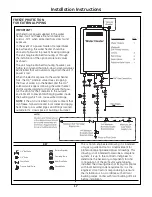
Page 16: ...of the particular system being installed The drawing does not imply compliance with local building code requirements it is the engineer s contractor s responsibility to ensure the installation is in accordance with all local building codes Confer with local building officials before installation 3 4 Ball Valve 3 4 Union Pressure Relief Valve Boiler Drain Valve KEY NOTE If unit is installed in an e...

Page 17: ... the outside environment to prevent discharging water inside the building which can cause water damage NOTE If the unit is installed in an environment that can freeze follow state and local codes and apply heat trace to ALL water pipes and fittings located outside attic crawl space or building structure 17 Installation Instructions This is not an engineered drawing it is intended only as a guide a...

Page 18: ...TRICAL REQUIREMENTS This appliance must be supplied with 120V 60Hz and connected to a properly grounded branch circuit protected by a 15 or 20 amp circuit breaker or time delay fuse If electrical supply provided does not meet the above specifications it is recommended that a licensed electrician install an approved outlet WARNING This water heater is equipped with a three prong grounding plug for ...

Page 19: ...t each VENTING INSTRUCTIONS Refer to the specific instructions on your vent product for additional installation requirements CONDENSATE Regions of cold climate will create more condensate in the vent system Condensate formation can even occur in high efficiency direct vent appliances To prevent condensate damage follow these instructions First remove the black plastic cap and use 5 8 ID flexible P...

Page 20: ...vent top to the water heater Lift up the female vent top and reposition as desired or replace with a male vent top Install the 4 screws at the vent top and tighten the 4 screws at the bracket Secure the first vent component to the water heater with one self tapping screw at the hole located above the condensate collector 5 4 3 2 1 Bracket MANUFACTURER PRODUCT PARTS Ubbink Rolux Vent System Refer t...

Page 21: ...i Connect Kit AGTCK1 and the Multi Connect Cable Kit AGTMC1 are optional accessories that connect 3 to 5 water heaters and allow them to function as one hot water source Refer to the instructions that come with the accessory for complete installation information GUIDELINES Do not install the Dual Connect Cable Kit AGTDC1 with the Multi Connect Kit AGTCK1 and the Multi Connect Cable Kit AGTMC1 beca...

Page 22: ...nected to the water heater Wire Controllers in Parallel NUMBER OF WIRED MAXIMUM CABLE LENGTH FOR EACH CONTROLLERS CONTROLLER TO WATER HEATER 1 328 ft 100 m 2 164 ft 50 m 3 or 4 65 ft 20 m REMOTE CONTROLLER INSTALLATION cont MOUNTING THE CONTROLLER Determine a suitable location for the controller Mount a single gang outlet box in the wall where the remote control is indicated Run the cable between ...

Page 23: ...T outlet and COLD inlet water lines to ensure they have not been crossed and are leak free Ensure the manual gas valve packaged with the water heater is installed in the gas supply line see page 12 Ensure the controller is installed and functioning Instruct the consumer on how to operate the controller Instructions are always supplied in the Owner s Manual see page 22 A typical water temperature s...

Page 24: ...24 Installation Instructions TECHNICAL DATA PRESSURE DROP CURVE OUTLET FLOW DATA GN75 GN94 GP94 GN75 GN94 GP94 ...

Page 25: ...LADDER DIAGRAM 25 Installation Instructions ...

Page 26: ...26 Notes ...

Page 27: ...27 Notes ...

Page 28: ...28 Notes ...

Reviews: