


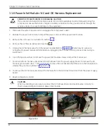
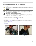
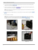


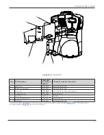


11.8 Power Supply Replacement
SENSITIVE TO ELECTROSTATIC DISCHARGE CAUTION
This procedure includes ESD sensitive parts. ESD control guidelines must be followed during this
procedure to ensure that static charges are safely conducted to the ground and not through the
sensitive device, to prevent damage to the equipment.
1. Make sure the system power cord is unplugged from the power outlet.
2. Remove the unit cover as instructed in section 11.5.
3. Remove the LED driver board as instructed in section 11.7.
4. Use a 5.5mm nut driver to remove the nuts that attach the power supply board to the back plate to
release it.
5. Reverse steps to re-install.
71
Chapter 11: Replacement Procedures
Summary of Contents for Giraffe Blue Spot PT Lite
Page 1: ...Giraffe Blue Spot PT Lite Operation Maintenance and Service Manual GE Healthcare ...
Page 7: ... 7 Part I Operation and Maintenance ...
Page 8: ...8 Part I Operation and Maintenance This page is intentionally left blank ...
Page 16: ...This page is intentionally left blank 16 Chapter 1 Product Overview ...
Page 22: ...This page is intentionally left blank 22 Chapter 2 Product Setup and Operation ...
Page 26: ...This page intentionally left blank 26 Chapter 3 Operator s Maintenance ...
Page 32: ...This page intentionally left blank 32 ...
Page 33: ... 33 Part II Service ...
Page 34: ...34 Part II Service This page is intentionally left blank ...
Page 44: ...44 Important Service Safety Information This page is intentionally left blank ...
Page 50: ...This page is intentionally left blank 50 Chapter 7 Installation ...
Page 55: ...Chapter 9 Calibration No calibration is required for the Giraffe Blue Spot PT Lite 55 ...
Page 56: ...This page is intentionally left blank 56 Chapter 9 Calibration ...
Page 72: ...This page is intentionally left blank 72 Chapter 11 Replacement Procedures ...
Page 88: ...12 5 Wiring Diagram 88 Chapter 12 Service Parts ...
Page 94: ...This page intentionally left blank 94 ...
Page 95: ......


