


Installation Instructions
6
7
6
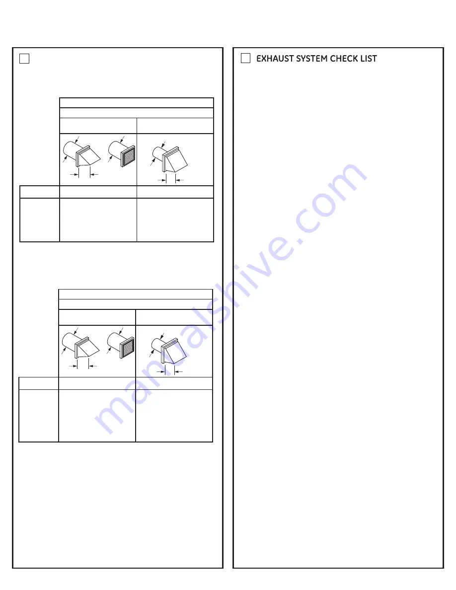
EXHAUST INFORMATION
(cont.)
EXHAUST LENGTH
4" DIA.
4"
4" DIA.
4" DIA.
2-1/2"
RECOMMENDED MAXIMUM LENGTH
Exhaust Hood Types
Recommended
No. of 90 º
Elb ows
Rigid
Metal
Rigid
Metal
150 Feet
135 Feet
125 Feet
115 Feet
0
1
2
3
Use only for sho rt
run installations
4
5
105 Feet
95 Feet
125 Feet
115 Feet
105 Feet
95 Feet
85 Feet
75 Feet
NORMAL VENT
LONG VENT
EXHAUST LENGTH
4" DIA.
4"
4" DIA.
4" DIA.
2-1/2"
RECOMMENDED MAXIMUM LENGTH
Exhaust Hood Types
Recommended
No. of 90 º
Elb ows
Rigid
Metal
Rigid
Metal
90 Feet
60 Feet
45 Feet
35 Feet
0
1
2
3
Use only for sho rt
run installations
4
25 Feet
60 Feet
45 Feet
35 Feet
25 Feet
15 Feet
ONLY THESE MODELS
GTDL740EDWW
GTDL740GDWW
SEALING OF JOINTS
?
All joints should be tight to avoid leaks. The male end of each
section of duct must point away from the dryer.
?
The duct shall not be assembled with screws or other
fastening means that extend into the duct and catch lint.
?
Duct joints can be made air and moisture-tight by wrapping
the overlapped joints with duct tape.
?
Horizontal runs should slope down toward the outdoors
1/4 inch per foot.
INSULATION
Duct work that runs through an unheated area or is near air
conditioning should be insulated to reduce condensation and
lint build-up.
HOOD OR WALL CAP
?
Terminate in a manner to prevent back drafts or entry of birds
or other wildlife.
?
Termination should present minimal resistance to the exhaust
air flow and should require little or no maintenace to prevent clogging
?
Never install a screen in or over the exhaust duct. This could
cause lint build up.
?
Wall caps must be installed at least 12 in. above ground level
or any other obstruction with the opening pointed down.
SEPARATION OF TURNS
For best performance, separate all turns by at least 4 ft. of straight
duct, including distance between last turn and exhaust hood.
TURNS OTHER THAN 90º
?
One turn of 45º or less may be ignored.
?
Two 45º turns should be treated as one 90º turn.
?
Each turn over 45º should be treated as one 90º turn.
PARTS AVAILABLE FROM LOCAL SERVICE
ORGANIZATIONS
?
Rigid Metal Duct Components
WX8X63
4
ʺ
x 1
ʹ
Duct
WX8X64
4
ʺ
x 2
ʹ
Duct
WX8X51
4
ʺ
Elbow
WX8X59
4
ʺ
Aluminum Hood
?
Flexible Metal Duct Components
WX8X58
4
ʺ
Clamps (2)
WX8X59
4
ʺ
Aluminum Hood
WX08X10077
6
ʹ
UL-Listed, Flexible Metal (Semi-Rigid)
Duct, 2 Clamps, 2 Close Elbows
WE1M454 Cover rear exhaust opening
For every extra 90° elbow, reduce the allowable vent system
length by 10 ft.
Two 45° elbows will be treated like one 90° elbow.
For the side exhaust installations, add one 90° elbow to the
chart.
The total vent system length includes all the straight portions
and elbows of the system (transition duct included).