background image

03

04

3 Product Introduction
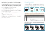
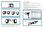
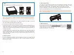
3.1 Intended Usage 

The GEP series which is a Three or Six MPPT,  three phase transformer-less grid-connected 
inverter which is a crucial unit between the PV string and the utility grid in the PV power system.
Inverter is dedicated to converting directing current generated by the PV module into alternating
current, and feeding it into the utility grid, this conforms to parameters of the local utility grid. The
intended usage of inverter is illustrated in the below figure.


kW.H

A

B

C

D


GEP series 
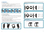
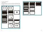
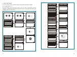
GEP12-L-10,GEP15-L-10,GEP20-L-10,GEP25-10,GEP30-10,GEP36-10,GEP29.9-10,GEP30-L-1
0,GEP35-L-10,GEP50-10,GEP60-10 support four different types(TN-S,TN-C,TN-C-S, TT) of grid. 
please refer to the below figure. 

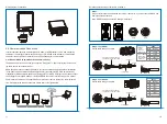
The reason why the inverter can't be connected to the PV module is that the positive or 
negative terminal should be grounded, except when a transformer has been used between 
the inverter and grid.

Item

A

B

C

D

Description

PV string

Inverter

Meter device

Utility grid

Note

Monocrystalline silicon, polycrystalline silicon and others.

GEP Series

Meter cupboard with distributed generation system

TN-S, TN-C, TN-C-S, TT, IT

(different Model types with different types of utility grid as below)

TN-S

TN-C

TN-C-S

TT

L1

L2

L3

N

PE


PE

Transformer

Inverter

Transformer

L1

L2

L3

PEN

PE


Inverter

L1

L2

L3

N

PE

Transformer

PE


Inverter

L1

L2

L3

N

Transformer

PE


Inverter

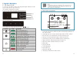
2 Safety Measures & Warning

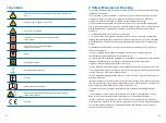
This manual contains important instructions for GEP series inverter that shall be followed during 
installation of the inverter.
The GEP series for Three or Six MPPT, Three-Phase solar inverter without transformer, which 
consists of  GEP12-L-10, GEP15-L-10, GEP20-L-10, GEP25-10, GEP30-10, GEP36-10, 
GEP29.9-10, GEP30-L-10,GEP35-L-10,GEP50-10 and GEP60-10 model type. 
GEP Series have been designed and tested strictly according to the international safety regula-
tion. As electrical and electronic equipment, safety instructions related to them must be complied 
with during installation, commissioning, operation. Incorrect or improper work may result in 
damage to:
1. The life and well-being of the operator or a third party.
2. The inverter and other properties that belong to the operator or a third party. Therefore the 
following safety instructions must be read and always kept in mind prior to any work. All detailed 
work-related safety warnings and notes will be specified at the critical points in corresponding 
chapter.
All installation and electrical work must only be performed by qualified personnel. They have:
•Been trained specially.
• Already completely read through and understood the manual and related documents.
• Be familiar with safety requirements for electrical systems.
The inverter must be installed and maintained by professionals in compliance with local electrical 
standards regulations and the requirements of local power authorities or companies.
• Improper handling of this device will pose a risk of injury.
• Always follow the instructions contained in the manual when moving or positioning the inverter.
• The weight of the equipment can cause injuries, serious wounds or bruise if improperly handled.
• Please install it in a place beyond children's reach.  
• Prior to installing and maintaining the inverter, it is crucial to make certain that the inverter in not 
electrically connected.
• Before maintaining the inverter, disconnect the connection between the AC grid and the inverter 
first, and then disconnect the connection between the DC input and the inverter, you should wait 
at least 5mins after these disconnection in case of electric shock.
• All cables must be firmly attached, undamaged, properly insulated, and adequately dimen-
sioned.
• The temperature of some parts of the inverter may exceed 60

 during operation. To avoid 

being burnt, do not touch the inverter during operation. Let it cool before touching it. 
• Without permission, opening the front cover of the inverter is not allowed. Users should not 
touch/replace any components of the inverter except the DC/AC connectors. Manufacturer will not 
bear any consequences caused by unauthorized actions which will lead to potential injury to 
people and damage to inverters.

• Static electricity may damage electronic components. Appropriate method must be adopted to 
prevent such damage to the inverter; otherwise the inverter may be damaged and the warranty 
will be annulled.
• Ensure that the output voltage of the proposed PV array is lower than the maximum rated input 
voltage of the inverter; otherwise the inverter may be damaged and the warranty will be annulled.
• If the equipment is used in a manner not specified by the manufacturer, the protection provided 
by the equipment may be impaired.
• When exposed to sunlight, the PV array will generate very high voltage which can cause 
electrical shock hazard. Please strictly follow the instruction we provided.
• PV modules should have an IEC61730 class A rating.
• Prohibit inserting or pulling the AC or DC terminals when the inverter is operational. Or the 
inverter will be destroyed.
Only DC connectors provided by Manufacturer are permitted for use, otherwise the inverter may 
be damaged and the warranty will be annulled.
• The inverter can exclude the possibility of DC residual currents to 6mA in the system,Where an 
external RCD is required in addition to the built-in RCMU, type A RCD must be used to avoid 
tripping.
• The default photovoltaic module is not grounded.
• It is recommended to add a fuse when there is more than two PV string inputs into one MPPT.
The IP65 premise is that the machine is completely sealed.  Please install it within one day after 
unpacking, otherwise please block the unconnected port and do not open it to ensure that the 
machine is not exposed to water and dust. 
 

Summary of Contents for GEP

Page 1: ...833 support au gesolarinverter com sales au gesolarinverter com Global Sales Service Network GEP 12 60KW THREE PHASE USER MANUAL GE is a registered trademark of General Electric Company and is used under license by Jiangsu GoodWe Power Supply Technology Co Ltd 2020 All Rights Reserved 340 00453 01 ...

Page 2: ...n 12 4 4 Communication Connection 17 5 System Operation 21 5 1 LCD Panel And LED 21 5 2 User Interface Introduction 22 5 3 System Configuration 25 5 4 Precaution For Initial Startup 29 5 5 Special Adjustable Setpoints 30 6 Troubleshooting 33 7 Technical Parameters Block Diagram 35 7 1 Technical Parameters 35 7 2 Block Diagram 39 8 Maintenance 40 8 1 Clearing The Fan 40 8 2 Checking The DC Switch 4...

Page 3: ...hapter All installation and electrical work must only be performed by qualified personnel They have Been trained specially Already completely read through and understood the manual and related documents Be familiar with safety requirements for electrical systems The inverter must be installed and maintained by professionals in compliance with local electrical standards regulations and the requirem...

Page 4: ... PE Inverter Static electricity may damage electronic components Appropriate method must be adopted to prevent such damage to the inverter otherwise the inverter may be damaged and the warranty will be annulled Ensure that the output voltage of the proposed PV array is lower than the maximum rated input voltage of the inverter otherwise the inverter may be damaged and the warranty will be annulled...

Page 5: ...485 WIFI for communication Inverters also provide running recode data display parameter configuration via LCD panel For the main block diagram please refer to chapter 7 2 3 3 2 Function Description Inverter functions can be grouped as following 1 Conversion function Inverter converts direct current power into alternating current power which conforms to the grid requirement of its installation coun...

Page 6: ... RS 485 DRED Communication Terminal Grounding Screw Expansion Bolt Safe Screw Connecting Terminal Grounding AC Cover WiFi Module WiFi communication Or without LCD Quick Installation Instruction Image shown here is for reference only the received products may be different 3 4 2 Identify The Inverter A nameplate is attached on the one side of the inverter It provides the information about the type o...

Page 7: ...llowing values The Upward part The downward part The front part Both sides Interval 200mm 500mm 500mm 600mm 1200mm 500mm 1200mm 600mm 600mm 500mm 200mm The Upward part The downward part The front part Both sides Interval 500mm 500mm 500mm 1000mm 1200mm 500mm 1200mm 1000mm 1000mm 500mm 500mm 4 Installation 4 1 Mounting Instructions 1 In order to achieve optimal performance the ambient temperature s...

Page 8: ...inverter and grid access point of the circuit breaker or fuse 5 It is recommended to use copper wire if you need to use aluminum wire please consult the inverter manufacturers 6 Follow these steps to connect the utility and inverter Step 1 Choose the appropriate communication cable and wire stripping out specifications please refer to the table below GEP12 20 L 10 GEP25 36 10 10 25 was 16 was reco...

Page 9: ...EP50 10 GEP60 10 Recommended Nominal Current Of AC Breaker 40A 50A 68A 50A 55A 60A 66A 100A 120A 100A 120A L1 L2 L1 1 2mm 2 Insert the stripped wire into the terminal and compress it tightly by crimping pliers Step 3 From the accessory bag terminal set on the wire and tool clamping Use tool clamp terminals If use line pressing pliers wire diameter smaller two separating crimping terminal shape rul...

Page 10: ...s not met The GEP series has three PV input area PV1 input PV2 input PV3 input each with MPPT tracker therefore the three PV input can be different with each other including different type of modules different numbers of connecting PV strings different orientation angel of PV modules There are four types of DC connectors DEVALAN MC4 AMPHENDL H4 and QC4 10 series NO A B C Name Cold pressed terminal...

Page 11: ...must be separated from other power cable to prevent the communication from being interfered RS485 connection please refer to the figure below Inverter RS485 EzLogger Pro RS485 RS485 PC Router Internet Inverter Inverter Detailed operation steps of series are as follows Step 1 Plug out the terminal and dismantle the resistor short wire if you want use the DRED and Remote shutdown function Note DRED ...

Page 12: ...ruction in the attachment and you can also refer to the description of Demo Videos Of Monitoring Installation on the http www goodwe com DownLoad aspx website After the configurations are completed please register on the website www gesolarinverter com The WiFi module installation of series is shown in the below figure 4 4 2 Earth Fault Alarm The inverter complies with IEC62109 2 13 9 When earth f...

Page 13: ...sponds to NOTE Download SolarGo App from Google Play Store or Apple App Store to complete the system operation if the inverter has no screen You can also scan the QR code to download it SolarGo APP 5 2 User Interface Introduction Communication information icon GPRS and WiFi show the signal strength RS485 shows the communication address Communication icon The way of communication There are GPRS WiF...

Page 14: ...iFi 22 93 3kWH 4 E TOTAL E DAY 01 01 2020 00 00 00 CARBON Fault Utility Loss 0 0kWH Basic Advanced WiFi 22 105 3kWH 4 E TOTAL E DAY 01 01 2020 00 00 00 Fault WiFi Configuration 22 Basic Advanced 01 01 2020 00 00 00 Fault WiFi Configuration 22 Vac1 2 3 0 0 0 0 0 0V Iac1 2 3 0 0 0 0 0 0A Fac1 2 3 0 00 0 00 0 00Hz Vpv1 2 3 0 0 0 0 0 0V Ipv1 2 3 0 0 0 0 0 0A Istr1 2 3 0 0 0 0 0 0A Istr4 5 6 0 0 0 0 0 0A...

Page 15: ...Grid Connection WiFi 22 01 01 2020 00 00 00 Fault Configuration Language Data Time Communication Country Code Grid Connection WiFi 22 01 01 2020 00 00 00 Fault Configuration Language Data Time Communication Country Code Grid Connection WiFi 22 01 01 2020 00 00 00 Fault Country Code Holland Northlreland ChinaHigher France 50Hz France 60Hz WiFi 22 01 01 2020 00 00 00 Fault Country Code Holland Northlr...

Page 16: ...l Adv Settings HVRT Grid Type Password Factory Data Reset WiFi 22 01 01 2020 00 00 00 Normal Adv Settings HVRT Grid Type Password Factory Data Reset WiFi 22 01 01 2020 00 00 00 Normal Reset Factory Data Reset Factory Data WiFi 22 01 01 2020 00 00 00 Normal Adv Settings Power Limit CT Ration PF Value Shadow LVRT WiFi 22 01 01 2020 00 00 00 Normal Power Limit OFF ON WiFi 22 01 01 2020 00 00 00 Norma...

Page 17: ...as trip points trip times recon nect times active and inactive QU curves and PU curves It is adjustable through special software If needed please contact after sales To obtain software manuals you can download them from the official website or contact after sales 5 5 1 PF Power Curve Mode PF power curve mode can be modified by Modbus communication method specifically according to the machine Modbu...

Page 18: ...ording to the set range to set the corresponding value QU curve Mode Function QU curve mode enable or disable V1 voltage ratio Q1 reactive power ratio V2 voltage ratio Q2 reactive power ratio V3 voltage ratio Q3 reactive power ratio V4 voltage ratio Q4 reactive power ratio Function Power recovery rate Settings Default value Australia 0 900 207V 300 30 Pn 957 220V 300 30 Pn 1087 250V 300 30 Pn 1152...

Page 19: ...isconnect DC switch check the insulation of PV string wiring to earth 2 Reconnect the DC switch again 3 If the problem still exists please call the local service office 1 Disconnect DC switch take off AC connector measure the voltage between line and neutral in connector make sure if it conforms to the grid connected specification of inverter 2 If it does not please check grid wiring 3 If it does ...

Page 20: ...EP25 10 is 25000W 2 For Brazil Max Output Apparent Power GEP25 10 is 25000W 3 For Brazil Nominal Output Voltage GEP25 10 is 380V GEP36 10 is 380V 4 For Brazil Communication GEP25 10 is RS485 WiFi USB PLC Optional GEP36 10 is RS485 WiFi USB PLC Optional Integrated Integrated Integrated Optional Type II Type II Integrated Integrated Integrated Integrated Class I C 30 60 0 100 3000 Fan Cooling RS485 ...

Page 21: ...Integrated Integrated Optional Type II Type I optional Type II Integrated Integrated Integrated Integrated Class I C 30 60 0 100 3000 Fan Cooling LCD LED or APP LED 55 520 660 220 IP65 1 Transformerless IEC62109 1 2 EN61000 6 1 EN61000 6 2 EN61000 6 3 EN61000 6 4 Technical Data PV String Input Data Max DC Input Power W Max DC Input Voltage V MPPT Range V Start up Voltage V Nominal DC Input Voltage...

Page 22: ...eaker Wait 5 minutes until the residual voltage has been released 8 1 Clearing The Fan Series inverter is equipped with three fans on its left side The fan intakes and handle covers should be cleaned yearly with a vacuum cleaner For more thorough cleaning completely remove the fans Disconnect the AC breaker first and then disconnect DC breaker Wait 5 minutes until the residual voltage has been rele...

Page 23: ...e Caution if there is no switch step 2 is not required Shutdown order 1 Turn off the breaker on AC side 2 Turn off the DC switch 3 Turn off the breaker on DC side Caution if there is no switch step 2 is not required 8 3 Checking The Electrical Connection 1 Check if the AC or DC wire is loose 2 Check if the earth wire is reliably grounded 3 Check if the waterproof covers of RS485 WiFi port are fasten ...

Page 24: ......

Reviews: