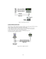
6.6 RS-485 PORT CONNECTION
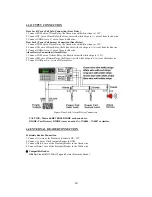
6.6.1 RS-485 CONNECTION(SINGLE UNIT)
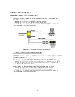
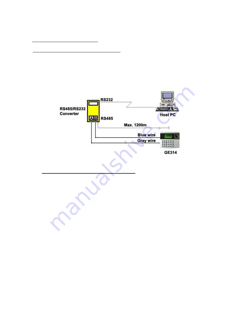
RS485/RS232 converter is required to use RS485 communication between the GE314 and a host PC.
Please follow the instructions.
1. Connect RS485-RTX(+), Grey wire to RS485-A port of the converter.
2. Connect RS485-RTX(-), Blue wire to RS485-B port of the converter.
3. Plug the RS232, 9-pin connector of the converter into the COM1 or COM2 Port of the host PC.
4. Install and run the GE314 Application Software.
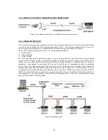
Figure: RS-485 Connection between GE314 and a host PC
6.6.2 RS-485 CONNECTIN(MULTIPLE UNITS)
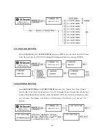
RS485/RS232 converter is required to use RS485 communication between multiple GE314 and a host PC.
Please follow the instructions.
First, you have to connect all RS485 port of GE314 in parallel. (max. 32 x GE314 Units)
1. Connect RS485-RTX(+), Grey wire of one GE314 to RS485-RTX(+), Grey wire of another GE314.
2. Connect RS485-RTX(-), Blue wire of one GE314 to RS495-RTX(-), Blue wire of another GE314.
3. Set a different COMM ID for each GE314.
Second, you have to connect one of RS485 port of GE314 to RS485/RS232 converter
.
1. Connect RS485-RTX(+), Grey wire of one GE314 to RS485-A port of the converter.
2. Connect RS485-RTX(-), Blue wire of one GE314 to RS485-B port of the converter.
3. Plug the RS232, 9-pin connector of the converter into the COM1 or COM2 Port of the host PC.
4. Install and run the GE314 Application Software.
20
Summary of Contents for GE314
Page 1: ...OPERATING MANUAL FINGERPRINT ACCESS CONTROLLER MODEL GE314 ...
Page 33: ...9 2 F2 SETUP MENU 33 ...
Page 37: ...9 3 F3 SETUP MENU 37 ...
Page 42: ...9 4 F4 SETUP MENU 9 4 1 ID REGISTRATION 1 Registration by RF Card 42 ...
Page 47: ...9 5 F5 SETUP MENU 9 5 1 TIME SCHEDULE 47 ...
Page 50: ...9 6 F6 SETUP MENU 50 ...
Page 53: ...9 7 F7 SETUP MENU 53 ...
Page 71: ...A S REQUEST FORM ORIGINAL 71 ...
Page 72: ...A S REQUEST FORM SAMPLE 72 ...
Page 73: ...MEMO 73 ...

